Microstrip antenna

A technology of microstrip antennas and antennas, which is applied in the directions of antennas, slot antennas, antenna arrays, etc., can solve the problem of increasing the antenna section and achieve the effect of reducing mutual coupling

Active Publication Date: 2020-05-15
SOUTHEAST UNIV +1
View PDF12 Cites 4 Cited by
  • Summary
  • Abstract
  • Description
  • Claims
  • Application Information

AI Technical Summary

Problems solved by technology

However, this method can only be applied to binary arrays, and the introduced radome increases the profile of the antenna

Method used


Image

  • Microstrip antenna
  • Microstrip antenna
  • Microstrip antenna

Examples


Embodiment Construction

[0029] The present invention will be further described below in conjunction with the accompanying drawings and embodiments.

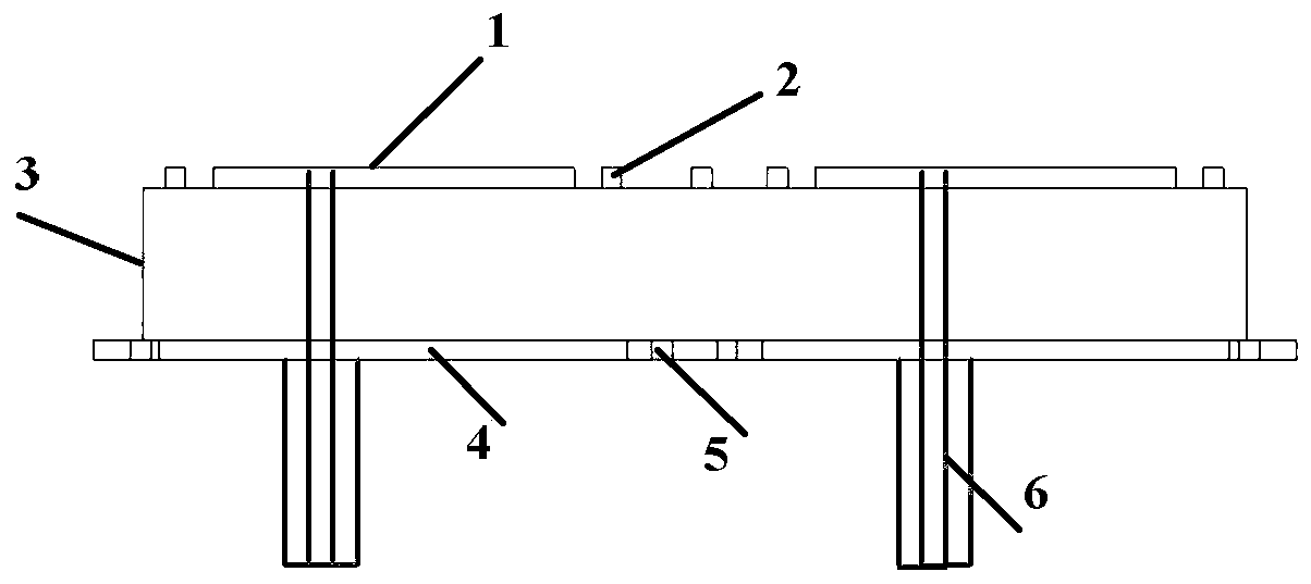
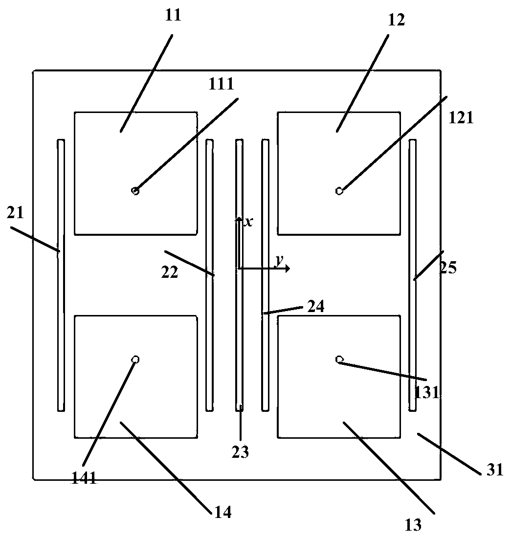
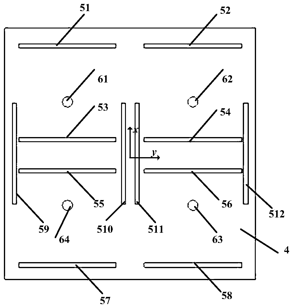
[0030] refer to figure 1 , figure 1 It is a schematic diagram of the side structure of a linearly polarized microstrip four-element antenna array loaded with a low-profile slot-metal strip combination array for decoupling proposed by the present invention. As shown in the figure, the antenna array includes an antenna patch 1 , a metal strip array 2 , a dielectric plate 3 , a reflection plate 4 , a slot array 5 , and a coaxial feeder 6 . The antenna patch 1 includes four array element patches in total. The antenna patch 1 is a copper layer with a thickness of 17 μm printed on the upper surface of the dielectric substrate 3 . The metal strip array 2 includes 5 metal strips in total, which are copper layers with a thickness of 17 μm printed on the upper surface of the dielectric substrate 3 , and the metal strip array 2 is coplanar with the antenna patc...


PUM

PropertyMeasurementUnit
thicknessaaaaaaaaaa
thicknessaaaaaaaaaa
dielectric lossaaaaaaaaaa

Abstract

The invention relates to the technical field of antenna desigh, and discloses a microstrip antenna which comprises a dielectric plate, an antenna patch positioned on the upper surface of the dielectric plate, a reflecting plate positioned on the lower surface of the dielectric plate and a coaxial feeder line for connecting the antenna patch with the reflecting plate. The microstrip antenna is characterized in that a metal band array coplanar with the antenna patch is also arranged on the upper surface of the dielectric plate, the metal band array comprises a first metal band located on the X axis of the antenna and a second metal band symmetrically surrounding the antenna patch with the first metal band as the symmetry axis, and the patch surrounding parts composed of the antenna patch andthe second metal band are formed at the two sides of the first metal band. According to a slot-metal band array provided by the invention, the mutual coupling between any two array elements in the 2*2 microstrip array can be reduced under the condition that the antenna profile is not increased and the port and the radiation performance of the antenna are not deteriorated.

Description

technical field [0001] The invention relates to the technical field of antenna design, in particular to a four-element linearly polarized microstrip antenna array with low profile and high isolation. Background technique [0002] Passive MIMO technology is a key technology in wireless communication applications. The multiple-input multiple-output technology improves the system capacity by utilizing multiple transmitting array elements and receiving array elements to realize multipath transmission. However, in the antenna array, the mutual coupling caused by space radiation and surface wave propagation will seriously deteriorate the radiation pattern and port matching characteristics of the antenna, thereby deteriorating the performance of the MIMO system. In addition, communication systems are increasingly integrated, electronic devices are required to have a smaller size, and the low-profile characteristics of antennas are becoming increasingly important. Therefore, an an...

Claims


Application Information

Patent Timeline
Patent Type & Authority Applications(China)
IPC IPC(8): H01Q1/38H01Q13/10H01Q21/06
CPCH01Q1/38H01Q13/106H01Q21/065
Inventor 高迪曹振新孙慜倩陈鹏全鑫
Owner SOUTHEAST UNIV
Why Eureka
Try Eureka