
Plate bending device for diesel generator production

A technology of diesel generator and bending device, applied in the direction of feeding device, positioning device, storage device, etc., can solve the problems of low work efficiency, inability to operate continuously, complex structure, etc., to improve work efficiency, reduce labor intensity, Avoid the effect of manual feeding

Inactive Publication Date: 2020-05-19
FUAN XINGSHIDAI MOTOR
View PDF8 Cites 8 Cited by
  • Summary
  • Abstract
  • Description
  • Claims
  • Application Information

AI Technical Summary

Problems solved by technology

[0002] A diesel generator is a combination of a diesel engine and an electric generator (usually an alternator) to produce electricity. Diesel compression ignition engines are usually designed to run on fuel oil, but there are types for other liquid fuels or natural gas. The basics of a diesel engine Structure: It is composed of cylinders, pistons, cylinder heads, intake valves, exhaust valves, piston pins, connecting rods, crankshafts, bearings and flywheels. At present, the production of diesel generators is commonly used in sheet bending devices, and sheet bending is usually It is the operator who holds the plate and then puts it into the bending operation of the bending machine. During the above operation, the plate must be held by the operator and fixed, including the operator also needs to hold it during the bending process. It can be seen that this increases the labor intensity of the operator, and the bending quality is completely determined by the operator's work experience. Continuous operation is not possible, the work efficiency is low, the bending effect is insufficient, time-consuming and laborious, and the use is inconvenient. complex

Method used


Image

  • Plate bending device for diesel generator production
  • Plate bending device for diesel generator production
  • Plate bending device for diesel generator production

Examples


Embodiment Construction

[0018] The following will clearly and completely describe the technical solutions in the embodiments of the present invention with reference to the accompanying drawings in the embodiments of the present invention. Obviously, the described embodiments are only some, not all, embodiments of the present invention. Based on the embodiments of the present invention, all other embodiments obtained by persons of ordinary skill in the art without making creative efforts belong to the protection scope of the present invention.

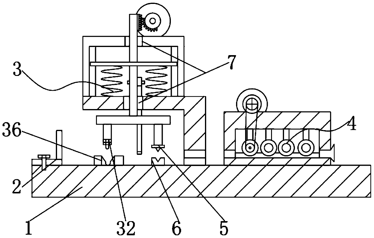
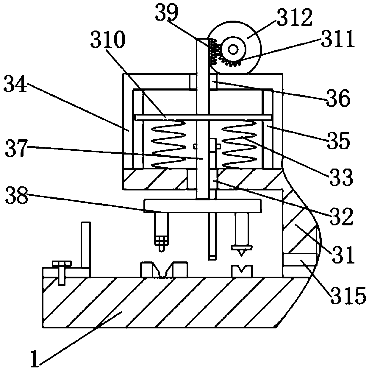
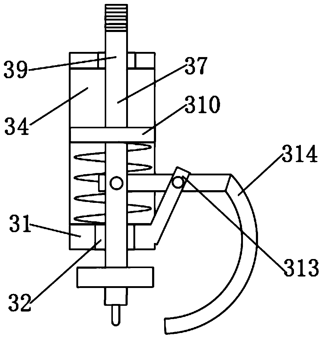
[0019] see Figure 1-4, the present invention provides a technical solution: a plate bending device for diesel generator production, including a workbench 1, a baffle plate 2, a bending assembly 3, a transmission assembly 4, a cutter 5, a cutting table 6 and a through hole 7 , the top outer wall of the workbench 1 is provided with a bending assembly 3; the bending assembly 3 includes an L-shaped mounting frame 31, a bending head 32, a spring 33, a first mounti...


PUM


Abstract

The invention discloses a plate bending device for diesel generator production. A conveying assembly comprises a second mounting frame, a conveying wheel, a rolling wheel, a first belt wheel, a firstfeeding port, a second belt, a groove, a second rotating motor, second belt wheels and a discharging port, wherein the second mounting frame is welded to the position, corresponding to an L-shaped mounting frame, of the outer wall of the top end of a workbench; the second rotating motor is fixed to the outer wall of the top end of the second mounting frame through bolts; the second belt wheels arefixed to the outer walls of the two sides of an output shaft of the second rotating motor in a sleeving manner; and the first feeding port is formed in the outer wall of one side of the second mounting frame in a penetrating manner. The plate bending device is provided with the conveying assembly, steel can be continuously conveyed and pressed to be straight, time and labor are saved, and manualfeeding is avoided; and the plate bending device is further provided with a bending assembly, the steel can be bent, cut off and replaced, the product quality and work efficiency are improved, use isconvenient, and the labor intensity of operators is relieved.

Description

technical field [0001] The invention relates to the technical field of diesel generator production equipment, in particular to a plate bending device for diesel generator production. Background technique [0002] A diesel generator is a combination of a diesel engine and an electric generator (usually an alternator) to produce electricity. Diesel compression ignition engines are usually designed to run on fuel oil, but there are types for other liquid fuels or natural gas. The basics of a diesel engine Structure: It is composed of cylinders, pistons, cylinder heads, intake valves, exhaust valves, piston pins, connecting rods, crankshafts, bearings and flywheels. At present, the production of diesel generators is commonly used in sheet bending devices, and sheet bending is usually It is the operator who holds the plate and then puts it into the bending operation of the bending machine. During the above operation, the plate must be held by the operator and fixed, including the...

Claims


Application Information

Patent Timeline
Patent Type & Authority Applications(China)
IPC IPC(8): B21D5/02B21D5/00B21D1/02B21D21/00B21D43/08B21D43/28
CPCB21D1/02B21D5/002B21D5/0209B21D21/00B21D43/08B21D43/287
Inventor 滕达
Owner FUAN XINGSHIDAI MOTOR
Learn More