Eureka AIR delivers breakthrough ideas for toughest innovation challenges, trusted by R&D personnel around the world.

Combined fully-automatic crystal rod grinding and polishing integrated machine

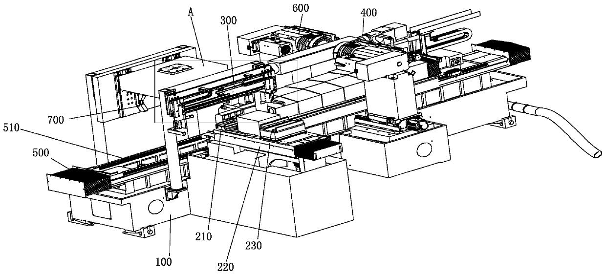
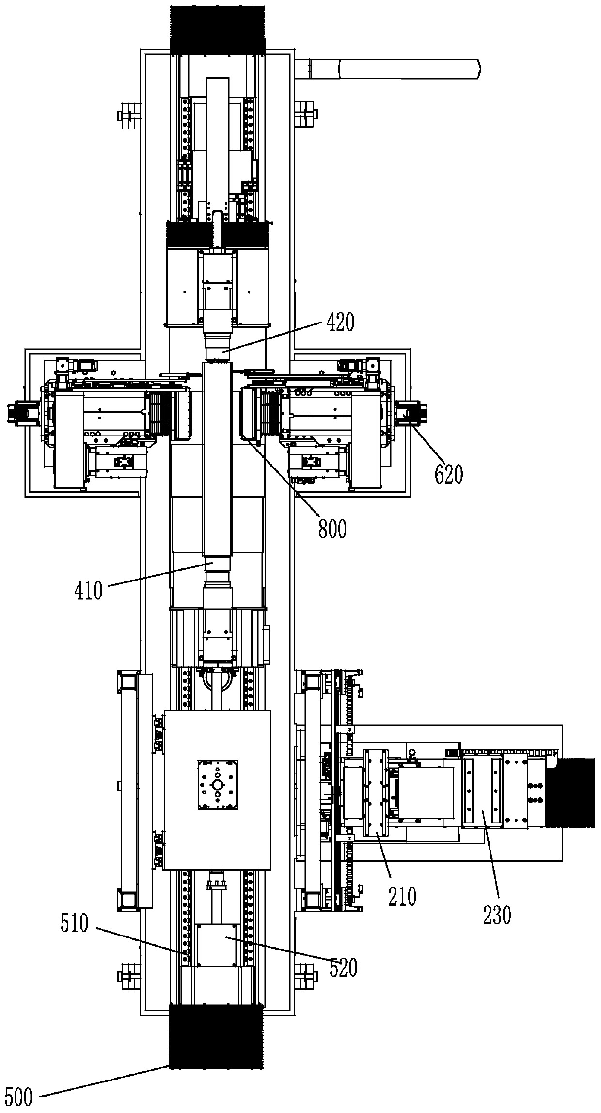
A fully automatic, combined technology, used in grinding/polishing equipment, grinding machine parts, surface polishing machine tools, etc., can solve the problems of low grinding process efficiency, large machining allowance, and increased number of knives

Pending Publication Date: 2020-05-19
QINGDAO GAOCE TECH CO LTD
View PDF0 Cites 7 Cited by
  • Summary
  • Abstract
  • Description
  • Claims
  • Application Information

AI Technical Summary

Problems solved by technology

[0003] At present, the mainstream of the grinding process for silicon rod processing at home and abroad is two-side rough grinding and two-side fine grinding. The problem of bit assembly error, the problem that the coarse grinding head and the fine grinding head are not completely in the same horizontal plane
In order to ensure that the fine grinding can be completely ground in the grinding process, the rough grinding often leaves a large machining allowance, and the processing amount of silicon rods removed per knife in the finishing process is small, resulting in an increase in the number of knives that need to be processed in the grinding process, resulting in The efficiency of the grinding process is low, and the processing allowance is large, resulting in the loss of silicon material. In addition, the grinding wheel is used for fine grinding, which is affected by the clamping accuracy of the head and tail frame, and some parts cannot be ground.

Method used


Image

  • Combined fully-automatic crystal rod grinding and polishing integrated machine
  • Combined fully-automatic crystal rod grinding and polishing integrated machine
  • Combined fully-automatic crystal rod grinding and polishing integrated machine

Examples


Embodiment Construction

[0023] The following will clearly and completely describe the technical solutions in the embodiments of the present invention with reference to the accompanying drawings in the embodiments of the present invention. Obviously, the described embodiments are only some, not all, embodiments of the present invention. Based on the embodiments of the present invention, all other embodiments obtained by those skilled in the art without creative efforts fall within the protection scope of the present invention.

[0024] It should be noted that when an element is said to be "fixed" to another element, it may be directly on the other element, or there may be one or more intervening elements therebetween. When an element is referred to as being "connected to" another element, it can be directly connected to the other element or one or more intervening elements may be present therebetween. The terms "vertical", "horizontal", "left", "right", "upper", "lower", "inner", "outer", "bottom", et...


PUM


Abstract

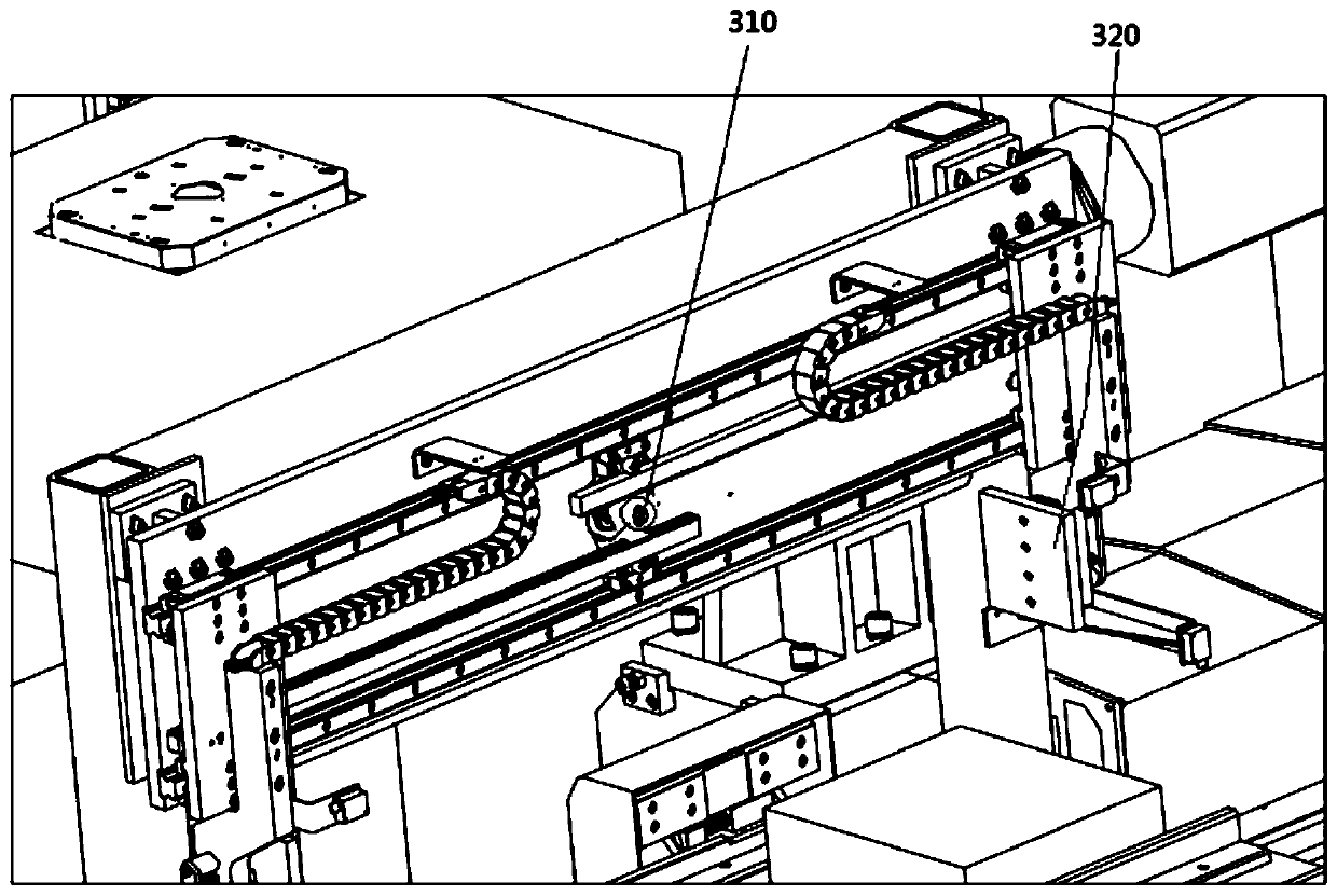
The invention discloses a combined fully-automatic crystal rod grinding and polishing integrated machine. The machine comprises a base, a feeding component and a discharging component which are used for feeding and discharging crystal rods, a crystal rod centering mechanism arranged on the base and used for realizing the crystal rod centering, a crystal rod clamping component arranged on the baseand used for clamping the crystal rods to move, a crystal rod longitudinal driving mechanism arranged on the base and used for driving the crystal rod clamping component to move in the longitudinal direction, a grinding and polishing head corresponding to a grinding and polishing station, and an adapter manipulator arranged on the base and used for transferring the processed crystal rods to the discharging component; the grinding and polishing head is driven by the grinding and polishing driving mechanism; and the number of the grinding and polishing head is the two groups, and the grinding and polishing heads are arranged correspondingly left and right. The machine has concentrated processing procedures, high workpiece accuracy retainability, and high processing efficiency, shortens silicon rod processing time, and reduces device costs. The machine is suitable for popularization and use.

Description

technical field [0001] The invention relates to the technical field of single crystal ingot processing equipment in the photovoltaic industry, in particular to a combined automatic ingot grinding and polishing machine. Background technique [0002] The grinding process of silicon wafers in the solar photovoltaic industry is a key process, and the processing technology is becoming more and more mature. With the new needs of industry development, reducing costs and improving production efficiency have become new demands of the industry. [0003] At present, the mainstream of the grinding process for silicon rod processing at home and abroad is two-side rough grinding and two-side fine grinding, which are the mainstream of the current grinding process in the photovoltaic industry; The problem of assembly error is that the coarse grinding head and the fine grinding head are not completely in the same horizontal plane. In order to ensure that the fine grinding can be completely ...

Claims


Application Information

Patent Timeline
IPC IPC(8): B24B5/50B24B5/35B24B29/08B24B41/06B24B41/00
CPCB24B5/355B24B5/50B24B29/005B24B29/08B24B41/00B24B41/06
Inventor 郭世锋徐公志于秀升尹美玲
Owner QINGDAO GAOCE TECH CO LTD
Why Eureka
Eureka Blog
Learn More