Cam Profile Detection System Driven by Wire Rope

A technology of cam profile and detection system, which is applied in the direction of measuring devices, instruments, and optical devices, etc., can solve the problems of not being able to adapt to the production of cam automatic lines, and achieve the effect of high cost performance, high precision and good precision retention

Inactive Publication Date: 2011-12-28
CHANGZHOU INST OF TECH
View PDF2 Cites 8 Cited by
  • Summary
  • Abstract
  • Description
  • Claims
  • Application Information

AI Technical Summary

Problems solved by technology

To achieve high-precision and high-efficiency detection of cams, correct processing and evaluation of its errors, and timely and rapid feedback of cam quality information, traditional optical-mechanical measuring instruments and manual data processing methods can no longer adapt to the wide range of cams. The need for automatic line production

Method used


Image

  • Cam Profile Detection System Driven by Wire Rope
  • Cam Profile Detection System Driven by Wire Rope
  • Cam Profile Detection System Driven by Wire Rope

Examples


Embodiment 1)

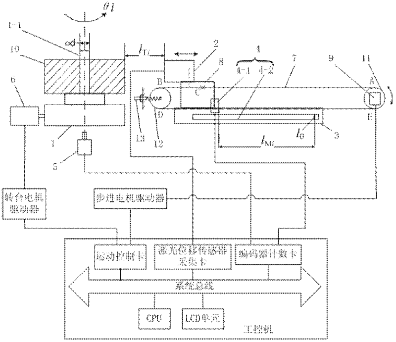
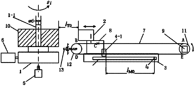
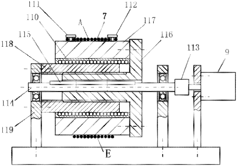
[0024] See Figure 1-2 , the wire rope-driven cam profile detection system of the present embodiment includes: a numerically controlled turntable 1 for driving the cam 10 to rotate horizontally and coaxially around a vertical mandrel 1-1, and a linear guide rail 3 horizontally arranged on one side of the numerically controlled turntable 1 , the slide block 8 located on the guide rail 3, the laser distance measuring head 2 located on the slide block 8 and on one side of the cam 10, the grating scale displacement for measuring the horizontal displacement of the laser distance measuring head 2 The sensor 4, the encoder 5 for detecting the rotation angle of the cam 10, the wire storage cylinder assembly 11 and the guide wheel 12 respectively arranged on both sides of the slider 8, elastically sleeved on the wire storage cylinder assembly 11 and the guide wheel The steel wire rope 7 fixedly connected with the slider 8 on the wheel 12 and the industrial computer; the wire storage cy...

Embodiment 2)

[0049] On the basis of Embodiment 1, this embodiment has the following modifications:

[0050] In order to eliminate the processing or installation error of the mandrel 1-1, which affects the accuracy of cam profile detection, the detection method of the cam profile detection device includes:

[0051] A. Detect the outer edge data of the mandrel 1-1: when the mandrel 1-1 starts to rotate a circle, the distance between the laser measuring head 2 and the outer circle of the mandrel 1-1 is the first distance Always control within the measuring range of the laser measuring head 2, and simultaneously detect and record the rotation angle θ i corresponding to the first spacing , and the slider 8 is in the horizontal direction with the hard zero The spacing of the second spacing ;

[0052] B. Fit the cam 10 on the spindle 1-1 without clearance, if the outer contour data of the cam 10 is known , then at the same time when the cam 10 is controlled to rotate one revolution, the...


PUM


Abstract

The invention provides a cam contour detection system which is driven by a wire rope and has simple structure, high detection precision and high efficiency. The system comprises the following parts: a numerical control rotary table used for driving a cam to carry out horizontal coaxial rotation around a vertical mandrel, a guide rail which is provided at one side of the numerical control rotary table horizontally, a slide block provided on the guide rail, a laser range finding head which is provided on the slide block and at one side of the cam, a raster ruler displacement sensor used for measuring horizontal displacement amount of the laser range finding head, an encoder used for detecting a rotation angle of the cam, a wire storage cylinder assembly and a directive wheel which are provided at two sides of the slide block respectively, a wire rope which is elastically sleeved on the wire storage cylinder assembly and the directive wheel, and is fixedly connected to slide block, and an industrial control computer. The wire storage cylinder assembly is in transmission connection with a stepping motor. The industrial control computer controls movement of the numerical control rotarytable and the stepping motor, and calculates outer contour data of the cam according to data measured by the laser range finding head, the raster ruler displacement sensor and the encoder.

Description

technical field [0001] The invention relates to a cam profile detection system driven by a wire rope. Background technique [0002] Cam mechanisms are widely used in various automatic machinery, precision instruments, automatic control systems, etc. To achieve high-precision, high-efficiency detection of cams, correct processing and evaluation of its various errors, and timely and rapid feedback of cam quality information, traditional optical-mechanical measuring instruments and manual data processing methods can no longer adapt to the wide range of cams. The need for automatic line production is adopted. With the rapid development of the automobile industry, engineering machinery, etc. and the continuous improvement of manufacturing technology, how to improve the detection accuracy and efficiency of cam machining accuracy is a technical problem to be solved in this field. Contents of the invention [0003] The technical problem to be solved by the present invention is t...

Claims


Application Information

Patent Timeline
Patent Type & Authority Applications(China)
IPC IPC(8): G01B21/20G01B11/02
Inventor 丁仕燕
Owner CHANGZHOU INST OF TECH
Why Eureka
Try Eureka