Composite floor slab splicing structure and construction method thereof and composite structure residential system

A technology of superimposing floor and floor, applied in the direction of floor, building structure, building components, etc., can solve the problems of low production efficiency of four-side rib, complex on-site construction of integral joint joints, etc., to reduce self-weight and concrete consumption, construction High efficiency and the effect of improving bending mechanical properties

Pending Publication Date: 2020-05-19
SHENZHEN YJY BUILDING TECH +2
View PDF0 Cites 2 Cited by
  • Summary
  • Abstract
  • Description
  • Claims
  • Application Information

AI Technical Summary

Problems solved by technology

[0005] The purpose of the present invention is to provide a superimposed floor splicing structure and its construction method and combined structure housing system, so as to so

Method used


Image

  • Composite floor slab splicing structure and construction method thereof and composite structure residential system
  • Composite floor slab splicing structure and construction method thereof and composite structure residential system
  • Composite floor slab splicing structure and construction method thereof and composite structure residential system

Examples


Embodiment 1

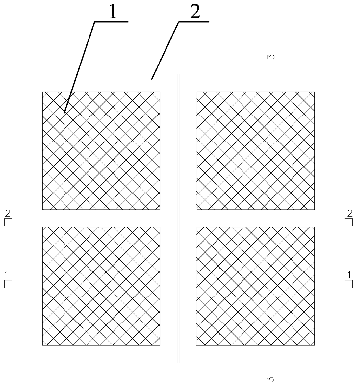
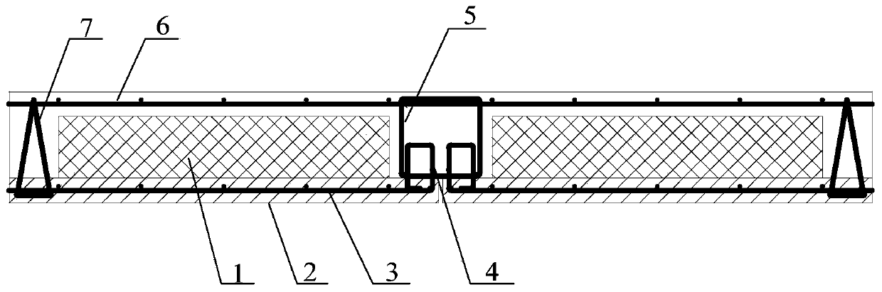
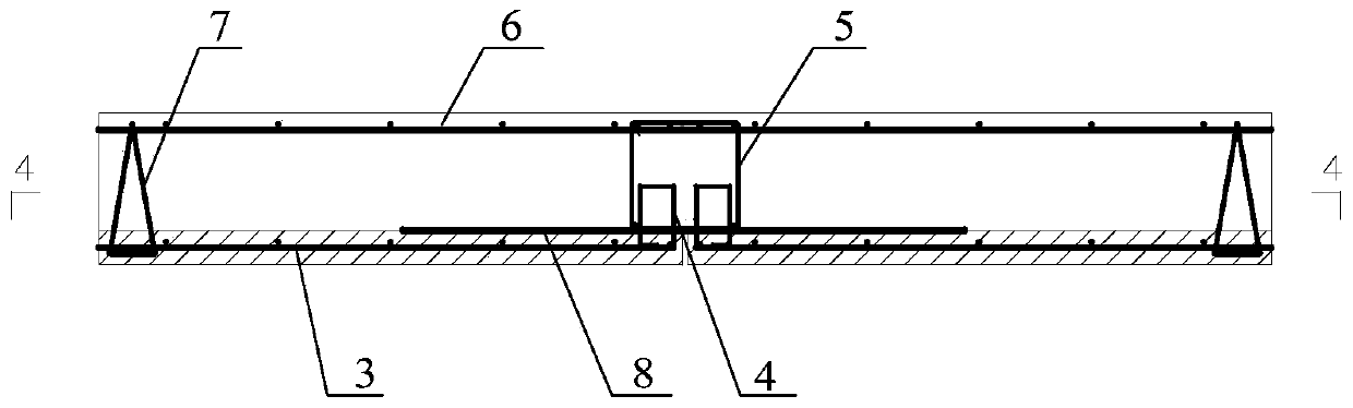
[0106] Such as Figure 1-Figure 7 As shown, the superimposed floor splicing structure provided by this embodiment includes a steel frame and two spaced floor slabs; the floor is located at one end of the splicing surface with an installation gap; the bottom of the installation gap is along the length of the floor splicing surface, in sequence Floor ring ribs 4 are vertically fixed at intervals; the reinforcing bar frame includes connecting horizontal ribs 9 arranged along the length of the splicing surface and a plurality of connecting ring ribs 5 fixed to the connecting horizontal ribs 9; the connecting ring ribs 5 are parallel to the floor ring ribs 4; The multiple connecting ring reinforcements 5 and the multiple floor ring reinforcements 4 on the two floor slabs are arranged in a staggered manner; the connecting ring reinforcement 5 and the floor ring reinforcement 4 are poured with concrete 12.

[0107] In the splicing structure of the superimposed floor slab provided in this...

Embodiment 2

[0157] This embodiment provides a composite structure residential system, which includes: steel beams, columns, shear walls, laminated floor slabs and cantilever slabs; the laminated floor slab has the laminated floor structure disclosed in Embodiment 1.

[0158] Such as Figure 27 As shown, in the horizontal projection plane, the floor structure 50 of the combined structure residential system includes a laminated floor 51 arranged indoors and a cantilever 52 arranged outdoors; the laminated floor 51 and the cantilever 52 are protected from cold and heat. The bridge node 53 is connected.

[0159] Such as Figure 28 with 29 As shown, the anti-cold and heat bridge node 53 includes a sandwich plate, a first steel backing plate 53c and a second steel backing plate 53d; the sandwich plate includes a first metal panel 53a, a second metal panel 53b, a plurality of node connectors 56, and a ring The sealing plate 54 and the heat-insulating material 55 (ie heat-insulating material); the ann...

Embodiment 3

[0168] This embodiment discloses a combined structure housing system. This embodiment is basically the same as Embodiment 2, except for the following:

[0169] Such as Figure 30 As shown, the combined structure residential system includes a restraining support 60; the two ends of the restraining support 60 are respectively fixedly connected to the middle part of the column and the middle part of the steel beam.

[0170] Such as Figure 31 As shown, the constraining support 60 includes an outer constraining sleeve 61 and an inner core 62, a constraining ring 63, and a constraining rod 64 that are all arranged in the outer constraining sleeve.

[0171] The restraint rod 64 and the inner core 62 are both arranged along the length direction of the outer restraint sleeve. The restraint ring 63 is fixed to the outer restraint sleeve, and is sleeved outside the inner core 62 and the restraint rod 64 to fix the inner core 62 and the restraint rod 64 .

[0172] As shown in 31, the inner core ...


PUM


Abstract

The invention relates to the technical field of buildings, in particular to a composite floor slab splicing structure and a construction method thereof and a composite structure residential system. The composite floor slab splicing structure comprises a reinforcement cage and two floor slabs arranged at an interval, wherein a mounting gap is formed in the end, positioned at a splicing surface, ofeach of the floor slabs; floor slab ring ribs are sequentially and vertically fixed at the bottom of the mounting gap at intervals; the reinforcement cage comprises a connecting horizontal rib and a plurality of connecting ring ribs; the connecting ring ribs and a plurality of floor slab ring ribs on the two floor slabs are arranged in a staggered manner; and concrete is poured in the connecting ring ribs and the floor slab ring ribs. The composite floor slab splicing structure greatly increases the onsite construction speed, lowers the construction difficulty and is simple in construction process; ribs do not go out of four sides of a prefabricated slab, so that factory automatic mass production is facilitated, and the production cost is greatly lowered; the composite floor slab splicingstructure is excellent in mechanical property, high in integrality, and also high in assembling integral type structural integrity; and onsite prefabricated construction is realized, the constructionefficiency is high, and dense rib construction greatly lowers the floor dead weight and concrete quantity to lower the cost.

Description

Technical field [0001] The invention relates to the field of construction technology, in particular to a superimposed floor splicing structure, a construction method thereof, and a combined structure residential system. Background technique [0002] The cast-in-place floor slab has the advantages of good structural integrity and good seismic performance, but it is laborious, requires a large number of templates, and has a long construction period, making it difficult to achieve industrial production. Prefabricated floor slabs are easy to realize the industrialization of building components, and the production of components is not restricted by seasons and climates, which can improve the quality of components, and the construction speed is fast, which can save a lot of templates and supports, but the integrity is poor, which is not conducive to earthquake resistance and poor permeability. Laminated slabs can combine the advantages of cast-in-place slabs and prefabricated slabs, an...

Claims


Application Information

Patent Timeline
IPC IPC(8): E04B1/00E04B5/17
CPCE04B1/00E04B5/17
Inventor 龚超张素梅侯兆新王月栋李孝忠
Owner SHENZHEN YJY BUILDING TECH
Why Eureka
Try Eureka