
LED display module and LED display screen

A display module and LED chip technology, applied in the direction of instruments, identification devices, etc., can solve problems such as poor bonding, low reliability of LED display modules, stress cracking, etc., achieve good sharpness, and reduce the probability of stress cracking , The effect of reducing thermal stress

Inactive Publication Date: 2020-05-19
SHENZHEN ABSEN OPTOELECTRONIC CO LTD +1
View PDF9 Cites 10 Cited by
  • Summary
  • Abstract
  • Description
  • Claims
  • Application Information

AI Technical Summary

Problems solved by technology

[0006] The purpose of the present invention is to provide an LED display module and an LED display screen, aiming to solve the problems caused by poor bonding or stress cracking at the interface between the face mask and the transparent encapsulant in the LED display module in the prior art. The technical problem of low reliability of LED display module

Method used


Image

  • LED display module and LED display screen
  • LED display module and LED display screen
  • LED display module and LED display screen

Examples


Embodiment Construction

[0036] Embodiments of the present invention are described in detail below, examples of which are shown in the drawings, wherein the same or similar reference numerals designate the same or similar elements or elements having the same or similar functions throughout. Attached below by reference Figure 3-6 The described embodiments are exemplary and are intended to explain the present invention, but should not be construed as limiting the present invention.

[0037] In describing the present invention, it should be understood that the terms "length", "width", "upper", "lower", "front", "rear", "left", "right", "vertical", The orientation or positional relationship indicated by "horizontal", "top", "bottom", "inner", "outer", etc. are based on the orientation or positional relationship shown in the drawings, and are only for the convenience of describing the present invention and simplifying the description, rather than Nothing indicating or implying that a referenced device or...


PUM


Abstract

The invention belongs to the technical field of LED display screens, in particular to an LED display module and an LED display screen. The LED display module comprises a circuit board, a packaging assembly, a plurality of LED chips and a plurality of driving ICs. The packaging assembly comprises a transparent packaging layer, a blocking part and an optical layer, the transparent packaging layer ispackaged on the circuit board, grooves are formed in the surface, opposite to the circuit board, of the transparent packaging layer at intervals, the grooves divide the surface of the transparent packaging layer into a plurality of light transmitting parts, and the light transmitting parts are packaged on the LED chips in a one-to-one correspondence mode; the grooves are filled with the blockingparts in a one-to-one correspondence mode, the optical layer is packaged on the surface, back on to the circuit board, of the transparent packaging layer, and the blocking parts are connected with theoptical layer. Due to the fact that the matrix resin of the blocking part, the matrix resin of the optical layer and the matrix resin of the transparent packaging layer are the same in thermal expansion coefficient, thermal stress in the LED display module can be reduced, and therefore the thermal stability and reliability of the LED display module are improved.

Description

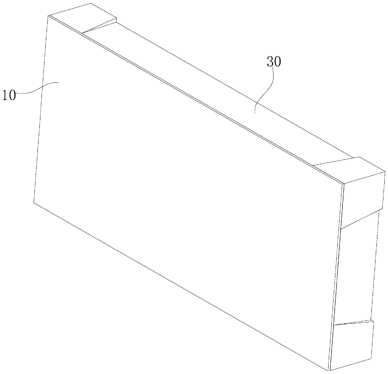
technical field [0001] The invention belongs to the technical field of LED display screens, in particular to an LED display module and an LED display screen. Background technique [0002] Currently, see figure 1 As shown, the LED (Light-Emitting Diode, light-emitting diode) display usually includes an LED display module 10 and a cabinet 30, the LED display module 10 is installed on the cabinet 30, and the display cabinet plays a role in supporting and fixing the LED display module. The role of group 10; with the continuous development of display technology, LED display screens are gradually developing towards higher density and smaller spacing. At present, the LED chip packaging methods on the LED display module 10 of the high-density LED display screen can be divided into two types: SMD (Surface Mounted Devices, surface mount device) and COB (Chip Oe Board, package on board). SMD also includes Top-SMD and Chip-SMD. Top-SMD uses a bracket as the LED chip carrier. The size ...

Claims


Application Information

Patent Timeline
Patent Type & Authority Applications(China)
IPC IPC(8): G09F9/33
CPCG09F9/33
Inventor 徐梦梦王爱玲
Owner SHENZHEN ABSEN OPTOELECTRONIC CO LTD
Learn More