Standby switching system for pneumatic regulating valves of continuous casting machine and control method of standby switching system

A switching system and continuous casting machine technology, applied in the field of iron and steel continuous casting, can solve the problems affecting the yield of molten steel and economic benefits, affecting the production rhythm of the continuous casting machine, loss of power and driving signals, etc., so as to improve the yield of molten steel. and economic benefits, the cooling method is stable and reliable, and the effect of ensuring the surface quality of the slab

Pending Publication Date: 2020-05-22
SHANDONG IRON & STEEL CO LTD
View PDF0 Cites 0 Cited by
  • Summary
  • Abstract
  • Description
  • Claims
  • Application Information

AI Technical Summary

Problems solved by technology

These two types of pneumatic control valves have fatal drawbacks in the production and application process. Once the PLC system has a hardware or network failure and shuts down, the power and drive signals of the multiple sector pneumatic control valves in the secondary cooling zone will be lost. If the amount of water is out of control, it will lead to breakouts, cracks in lying slabs or slabs
In order to minimize the loss, the continuous casting machine can only be shut down according to the accident, which will bring great economic losses, seriously affect the production rhythm of the continuous casting machine, and greatly affect the molten steel yield and economic benefits

Method used


Image

  • Standby switching system for pneumatic regulating valves of continuous casting machine and control method of standby switching system
  • Standby switching system for pneumatic regulating valves of continuous casting machine and control method of standby switching system
  • Standby switching system for pneumatic regulating valves of continuous casting machine and control method of standby switching system

Examples


Embodiment Construction

[0035] The following will clearly and completely describe the technical solutions in the embodiments of the present invention with reference to the accompanying drawings in the embodiments of the present invention. Obviously, the described embodiments are only some, not all, embodiments of the present invention. Based on the embodiments of the present invention, all other embodiments obtained by persons of ordinary skill in the art without making creative efforts belong to the protection scope of the present invention.

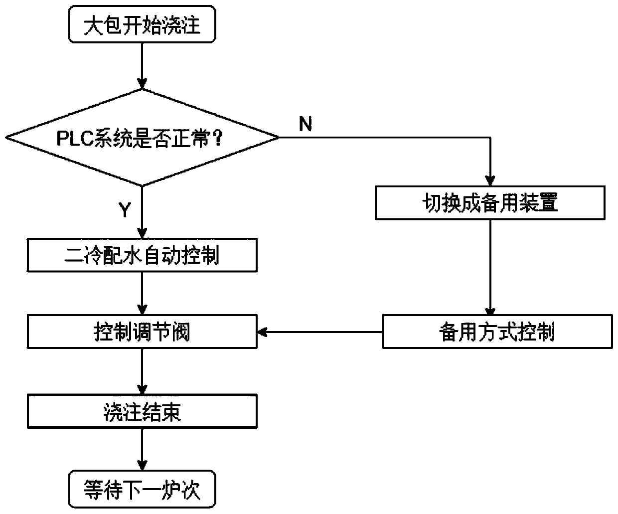
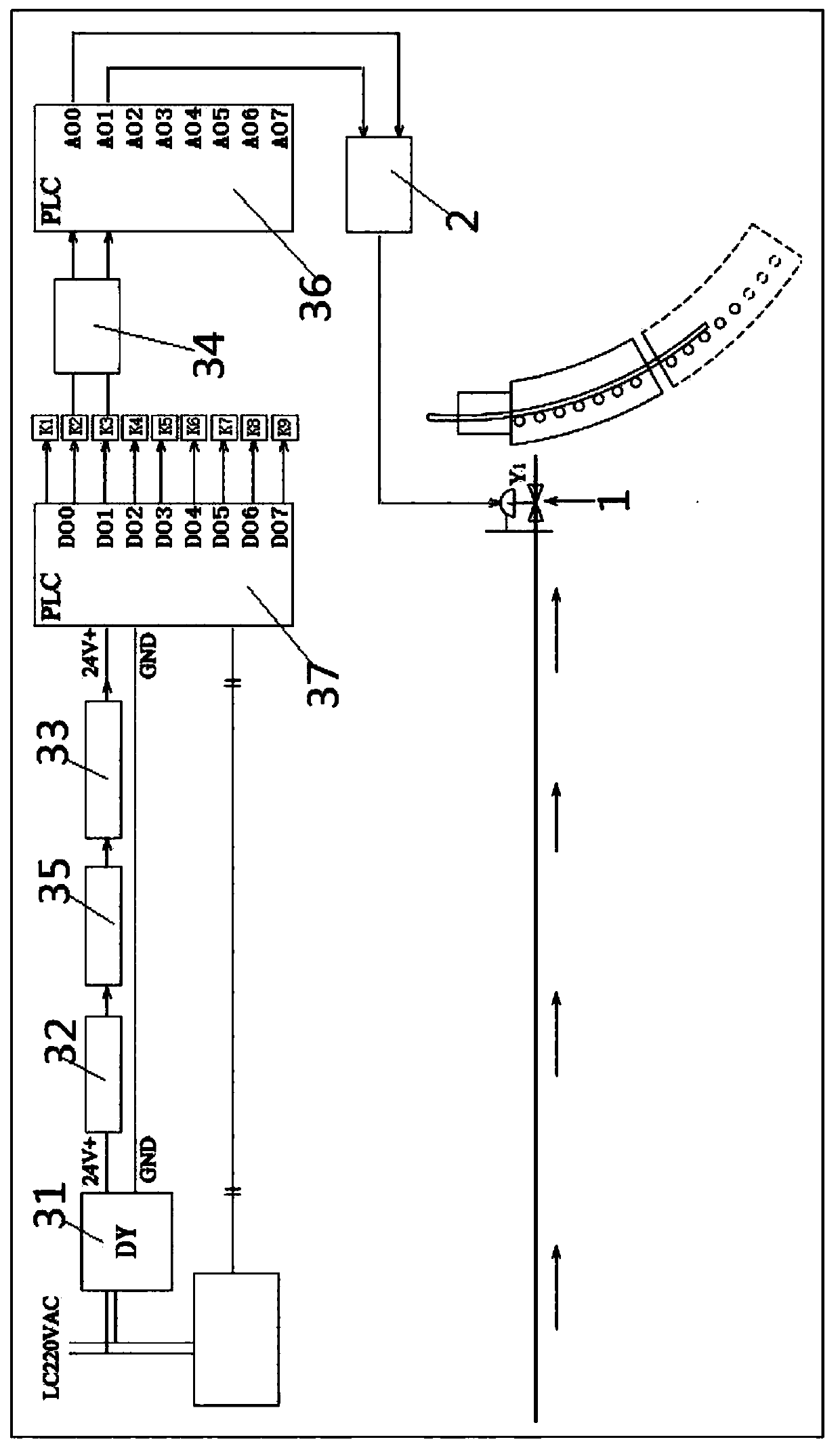
[0036] The core of the present invention is to provide a continuous casting machine pneumatic regulating valve standby switching system, which can make the casting slab cooling method stable and reliable, and can ensure the surface quality of the casting slab, ensure the production rhythm of the continuous casting machine, improve the yield of molten steel and economic benefits.

[0037] Another core of the present invention is to provide a control method appl...


PUM


Abstract

The invention discloses a standby switching system for pneumatic regulating valves of a continuous casting machine, and further provides a control method applied to the standby switching system. The standby switching system comprises pneumatic valves and a PLC. The PLC includes a power box, a main drive module, a valve control module, a standby drive module and a fault judgment module, wherein themain drive module, the valve control module and the standby drive module are electrically connected in sequence. The main drive module and the standby drive module are both electrically connected with a digital output module, so that the main drive module or the standby drive module is energized. The valve control module and the pneumatic valves are all electrically connected with an analog output module. The fault judgment module is used for detecting the running state and the network communication state of the PLC in real time, and controlling the main drive module to be energized when no fault occurs and controlling the standby drive module to be energized when a fault occurs. The standby switching system can enable the cooling mode of a casting blank to be stable and reliable, can guarantee the surface quality of the casting blank, and increases the yield of molten steel and economic benefits. The cooling mode of the casting blank can be stable and reliable.

Description

technical field [0001] The invention relates to the technical field of iron and steel continuous casting, and more specifically relates to a standby switching system for a pneumatic regulating valve of a continuous casting machine. In addition, it also relates to a control method applied to the backup switching system of the pneumatic regulating valve of the continuous casting machine. Background technique [0002] At present, during the production of continuous casting machines at home and abroad, the method of secondary cooling of the cast slabs of multiple sectors in the secondary cooling zone forming a solid slab shell is generally used to reduce the temperature. The main function of the secondary cooling water is to provide the cooling water required in the production process for multiple segments in the secondary cooling zone of continuous casting. The control effect of the secondary cooling water distribution in continuous casting directly affects the productivity of ...

Claims


Application Information

Patent Timeline
Patent Type & Authority Applications(China)
IPC IPC(8): B22D11/22B22D11/124
CPCB22D11/124B22D11/225
Inventor 蔡森郭秀辉王丽娟孙万岭杜彧杜芳蔡悝倪志国陈贤辉刘文鹏
Owner SHANDONG IRON & STEEL CO LTD
Why Eureka
Try Eureka