Ceramic tile cement pointing device for construction site

A technology for construction sites and ceramic tiles, which is applied in construction, building construction, etc., can solve problems such as low compaction efficiency, achieve the effects of saving cement materials, preventing cement overflow, and improving work efficiency

Inactive Publication Date: 2020-05-22
深圳市华建工程项目管理有限公司
View PDF1 Cites 1 Cited by
  • Summary
  • Abstract
  • Description
  • Claims
  • Application Information

AI Technical Summary

Problems solved by technology

[0005] Based on the technical problems of low manual compaction efficiency due to the need for compaction when performing white cement pointing on existing ceramic tiles, the present invention proposes a tile cement pointing device for construction sites

Method used


Image

  • Ceramic tile cement pointing device for construction site
  • Ceramic tile cement pointing device for construction site
  • Ceramic tile cement pointing device for construction site

Examples


Embodiment 1

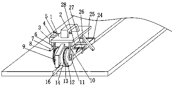
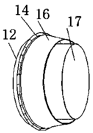
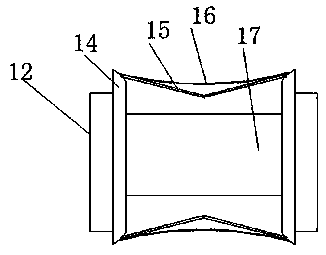
[0031] refer to Figure 1-6 , a tile cement pointing device for a construction site, comprising a fixed plate 1, a support rod 10 is welded on both sides of the bottom end of the fixed plate 1, and a rotating column 11 is connected to the bottom end of the support rod 10 through a rotating shaft. One end of the rotating column 11 is welded with a rotating block 12, the outer portion of the rotating block 12 is welded with a limiting ring 13, the outer portion of the limiting ring 13 is welded with a rubber ring 18, and the outer portion of the rubber ring 18 is welded with an arc-shaped rubber layer 14, Several bending rods 15 are welded between the two arc-shaped rubber layers 14, and the middle part of the bending rods 15 is provided with a torsion spring, and a connecting column 17 is welded between the two rotating blocks 12. There is a soft rubber layer 16. When the pressing device is used to joint the tile gap, the white cement will fall into the gap. At the same time, t...

Embodiment 2

[0040] refer to Figure 7 , a ceramic tile cement pointing device for a construction site. Compared with Embodiment 1, in this embodiment, in order to improve the stability of the power plate when the device is stirring, a rectangular strip 31 is welded on the inner wall of the top of the mixing chamber 3, and the mixing chamber 3 The inner wall is welded with a rubber clip 33 above the rectangular strip 31. The inside of the rubber clip 33 is provided with an arc-shaped slot 32. The outside of the power board 4 is provided with a rubber clip 34, and one side of the rubber clip 34 is There is an arc surface 35. When the motor 5 is turned on, due to the vibration of the motor 5 itself, the power plate 4 constantly vibrates at the top of the mixing chamber 3, and the rubber block 34 is engaged with the rubber clip 33, which improves the power plate 4 and the rubber clamping strip 33. The engagement ability of the stirring chamber 30 prevents the power plate 4 from being separate...


PUM


Abstract

The invention belongs to the technical field of construction equipment, particularly relates to a ceramic tile cement pointing device for a construction site, and aims at solving the technical problems that when existing ceramic tiles are subjected to white cement pointing, compaction treatment needs to be carried out, and the manual compaction efficiency is low. According to the scheme, the pointing device comprises a fixing plate, supporting rods are fixedly connected to the two sides of the bottom end of the fixing plate, the bottom ends of the supporting rods are rotationally connected with rotating columns through rotating shafts, one ends of the rotating columns are fixedly connected with rotating blocks, limiting rings are fixedly connected to the outer portions of the rotating blocks, rubber rings are fixedly connected to the outer portions of the limiting rings, arc-shaped rubber layers are fixedly connected to the outer portions of the rubber rings, and a plurality of bent rods are fixedly connected between the two arc-shaped rubber layers. According to the pointing device, through arranging an extrusion plate and a soft rubber layer, cement in a storage groove is extruded out through pressing the extrusion plate, meanwhile, in the process that the soft rubber layer is pushed by manpower, the functions of filling and smoothing cement in a gap are completed, and convenience of pointing work is improved.

Description

technical field [0001] The invention relates to the technical field of construction equipment, in particular to a ceramic tile cement pointing device for a construction site. Background technique [0002] Pointing refers to filling the gap between two adjacent masonry block materials with mortar. Its function is to effectively make the connection between the upper, lower, left, and right masonry block materials stronger and prevent wind and rain from invading the interior of the wall. , and make the wall clean, tidy and beautiful. [0003] After retrieval, the Chinese patent publication number is CN105777015B, which discloses a ceramic tile jointing agent and its preparation method. The ceramic tile jointing agent includes the following components in parts by weight: 30 to 40 parts of cement, 6 to 9 parts of quartz sand , 2 to 5 parts of iron oxide or titanium oxide, 3 to 6 parts of redispersible latex powder, 1.3 to 2.1 parts of hydroxypropyl methylcellulose, 0.4 to 0.7 pa...

Claims


Application Information

Patent Timeline
Patent Type & Authority Applications(China)
IPC IPC(8): E04F21/165
CPCE04F21/1652
Inventor 王焱金波李雯张政李子玉丁志雄
Owner 深圳市华建工程项目管理有限公司
Why Eureka
Try Eureka