
Method and device for actuating a camshaft adjuster

A camshaft adjuster and controller technology, which is applied in valve device, electrical control, control system, etc., can solve the problems of overheating, failure of the drive system, and the drive becomes hot, and achieve the effect of ensuring the starting ability.

Active Publication Date: 2020-05-22
VITESCO TECH GMBH
View PDF8 Cites 0 Cited by
  • Summary
  • Abstract
  • Description
  • Claims
  • Application Information

AI Technical Summary

Problems solved by technology

However, if this maximum power is required for a longer period of time, the drive can heat up so strongly that the drive system overheats and fails

Method used


Image

  • Method and device for actuating a camshaft adjuster
  • Method and device for actuating a camshaft adjuster
  • Method and device for actuating a camshaft adjuster

Examples


Embodiment Construction

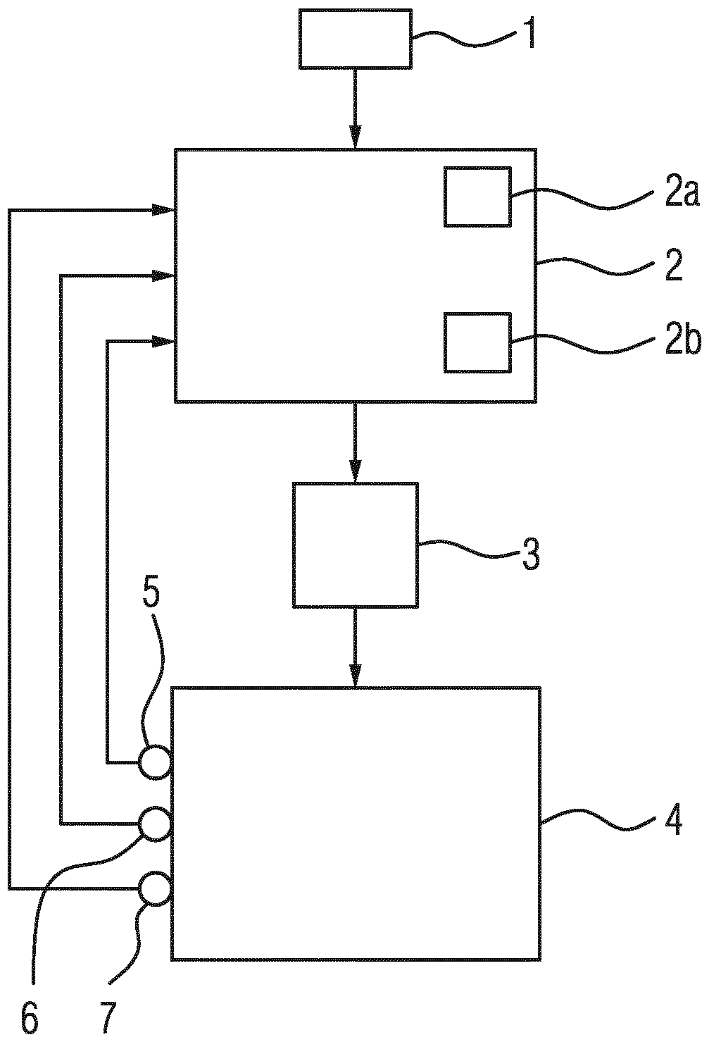
[0021] figure 1 A block diagram of a device for actuating a camshaft adjuster of an internal combustion engine is shown.

[0022] The shown device has a start / stop command transmitter 1, a control unit 2, a characteristic curve memory 2a, a non-volatile memory 2b, a camshaft adjuster electric motor 3, a camshaft adjuster adjusting unit 4, a current sensor 5 , temperature sensor 6 and actual position sensor 7. All the aforementioned components are integral parts of the internal combustion engine. The electric motor 3 and the adjusting unit 4 together form a camshaft adjuster.

[0023] Controller 2 is designed to carry out a method for actuating a camshaft adjuster, in which method an electric current is generated in electric motor 3 .

[0024] In this method, the controller 2 receives the actuation signal for the electric motor 3 in such a way that a current flows in the electric motor 3 of the camshaft adjuster.

[0025] The controller 2 ascertains the actuation signal for...


PUM


Abstract

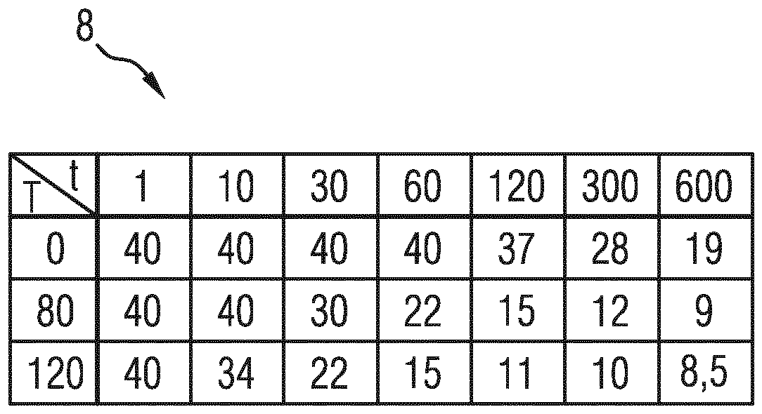
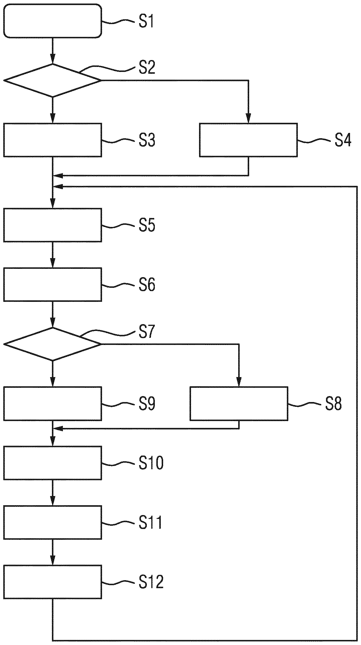
The invention relates to a method for actuating a camshaft adjuster of an internal combustion engine, in which a current flow is generated in an electric motor (3) of the camshaft adjuster, with the following steps: measuring the instantaneous current strength in the camshaft adjuster; calculating an average value of the measured current strength for a predefined time base; measuring the ambient temperature (T) of the camshaft adjuster; comparing the average value of the measured current strength with a threshold value taken from a characteristic field memory (2a) and associated with the measured ambient temperature (T) and the predefined time base; and reducing the instantaneous current strength in the camshaft adjuster, if the calculated average value of the current strength is greater than the associated threshold value. The invention also relates to a device for actuating a camshaft adjuster of an internal combustion engine.

Description

technical field [0001] The invention relates to a method and a device for actuating a camshaft adjuster. Background technique [0002] In motor vehicles, electric camshaft adjusters are increasingly being used to increase efficiency. With such a camshaft adjuster, a greater adjustment range with a later closing point of the intake camshaft is achieved than with a conventional hydrostatic adjuster. Other combustion methods can thus be used, for example according to the Atkinson cycle. [0003] DE 41 10 195 A1 discloses an adjusting device for two components in a rotational drive connection, in particular for adjusting a camshaft relative to a drive wheel driving the camshaft. Such an adjusting device has an adjusting gear arranged between a camshaft and a drive wheel driving the camshaft, which can be driven by an electric motor for adjustment. The stator of the electric motor is arranged in a fixed position. Together with the rotor of the electric motor, the adjusting ge...

Claims


Application Information

Patent Timeline
IPC IPC(8): F01L1/352H02P29/60
CPCF01L1/352F01L2800/01F01L2800/03F01L2820/032H02P29/60F01L1/344F02D13/02F01L9/20F01L2009/4094F01L2009/4088F01L9/40F01L2800/11F02D41/061F02D41/062F02D41/2422F02D41/2425F02D41/2429F02D41/2493F02D41/2496
Inventor W.施托瓦泽金锡周T.布克哈特
Owner VITESCO TECH GMBH
Learn More