

Water drainage pipeline mounting process
A drainage pipe and installation process technology, which is applied in the field of drainage pipe installation technology, can solve the problems of freezing expansion, drainage pipe cracking, and drainage pipe damage, etc., and achieve the effects of not being easy to freeze, blocking heat flow, and stabilizing the structure
- Summary
- Abstract
- Description
- Claims
- Application Information
AI Technical Summary
Problems solved by technology
Method used
Image

Examples
Embodiment 1-4
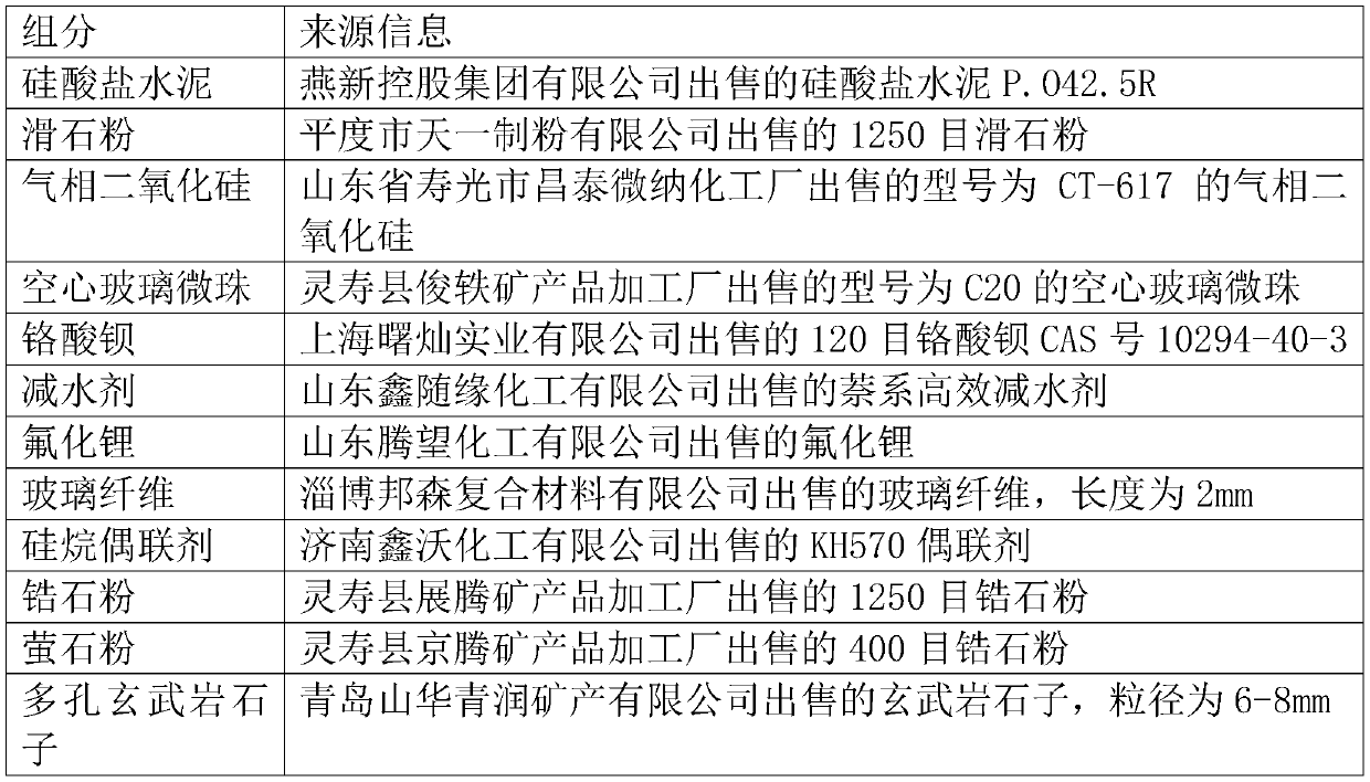
[0062] A thermal insulation coating, the thermal insulation coating comprises the following components:
[0063]Portland cement, talcum powder, fumed silica, hollow glass microspheres, barium complex acid, water, water reducing agent.
[0064] The input amount (unit Kg) of each component among the embodiment 1-4 is specifically shown in Table 2
[0065] Table 2
[0066]
[0067]
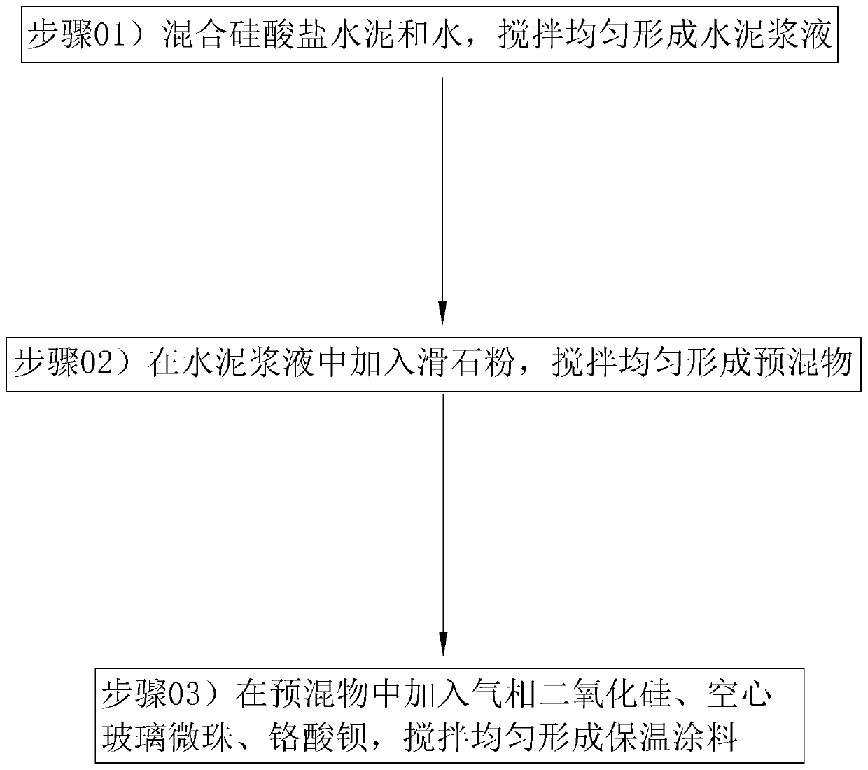
[0068] refer to figure 1 , the preparation method of thermal insulation coating in embodiment 1-4 comprises the following steps:
[0069] Step 01) Add Portland cement, water, and water reducing agent into the stirring tank at a rotating speed of 60r / min, and stir for 5min to form cement slurry;
[0070] Step 02) Add talcum powder into the cement slurry, rotate at a speed of 50r / min, and stir for 8min to form a premix;
[0071] Step 03) Add fumed silica, hollow glass microspheres, and barium complex to the premix at a rotation speed of 35r / min, and stir for 10 minutes to obtain the thermal i...
Embodiment 5-8
[0073] Compared with embodiment 4, the difference only lies in:
[0074] Insulation coating also comprises following component among the embodiment 5-8:
[0076] The input amount (unit Kg) of each component among the embodiment 5-8 is specifically shown in Table 3
[0077] table 3
[0078]
[0079]
[0080] Lithium fluoride is added into the premix together with fumed silica, hollow glass microspheres and barium complex acid in step 3) and stirred evenly.
Embodiment 9-12
[0082] Compared with embodiment 4, the difference only lies in:
[0083] Insulation coating also comprises following component among the embodiment 9-12:
[0084] Glass fiber, silane coupling agent.
[0085] The input amount (unit Kg) of each component among the embodiment 9-12 is specifically shown in Table 4
[0086] Table 4
[0087] Example 9 Example 10 Example 11 Example 12 Portland cement 100 100 100 100 talcum powder 170 170 170 170 fumed silica 70 70 70 70 hollow glass microspheres 28 28 28 28 barium complex 4.5 4.5 4.5 4.5 water 100 100 100 100 Superplasticizer 10 10 10 10 glass fiber 15 17.5 20 18 A silane coupling agent 1.5 1.75 2 1.8
[0088] The glass fiber and the silane coupling agent are added into the premix together with fumed silica, hollow glass microspheres and barium complex acid in step 3) and stirred evenly.
PUM
| Property | Measurement | Unit |
|---|---|---|
| Diameter | aaaaa | aaaaa |
Abstract
Description
Claims
Application Information