
Intelligent on-line monitoring system for pipe gallery

A technology for monitoring systems and pipe corridors, which is applied in the direction of measuring devices, instruments, and electric fire alarms, etc., and can solve problems such as loose fit, slow environmental parameters, slow temperature monitoring, etc.

Inactive Publication Date: 2020-05-26
北京泓业致联科技有限公司
View PDF6 Cites 8 Cited by
  • Summary
  • Abstract
  • Description
  • Claims
  • Application Information

AI Technical Summary

Problems solved by technology

[0003] For example, the current power utility gallery is monitored by point or line monitoring, that is, a monitoring point is set on the dome at a distance in the utility gallery, and a group of sensors are installed to monitor the environmental parameters in the utility gallery. In the underground pipe gallery, the anti-electromagnetic interference ability is poor, and in the natural state, it is relatively slow to the environmental parameters in the pipe gallery; and the line monitoring in the power pipe gallery, that is, one or two line sensors are installed outside the power transmission pipeline (Optical fiber temperature sensor) To monitor the temperature of the pipeline, the optical fiber temperature sensor not only needs to be installed along the entire pipeline, but also if the fiber optic temperature sensor at any point or section in the middle is not tightly attached to the pipeline, it will make the The temperature monitoring of points or sections is slow; moreover, the outer diameter of the delivery pipeline is large, if the surface far away from the fiber optic temperature sensor is locally high in temperature, the fiber optic sensor may not be able to detect it in time, and the reliability is poor

Method used


Image

  • Intelligent on-line monitoring system for pipe gallery
  • Intelligent on-line monitoring system for pipe gallery
  • Intelligent on-line monitoring system for pipe gallery

Examples


Embodiment Construction

[0029] Embodiments of the technical solutions of the present invention will be described in detail below in conjunction with the accompanying drawings. The following examples are only used to illustrate the technical solutions of the present invention more clearly, and therefore are only examples, rather than limiting the protection scope of the present invention.

[0030] It should be noted that, unless otherwise specified, the technical terms or scientific terms used in this application shall have the usual meanings understood by those skilled in the art to which the present invention belongs.

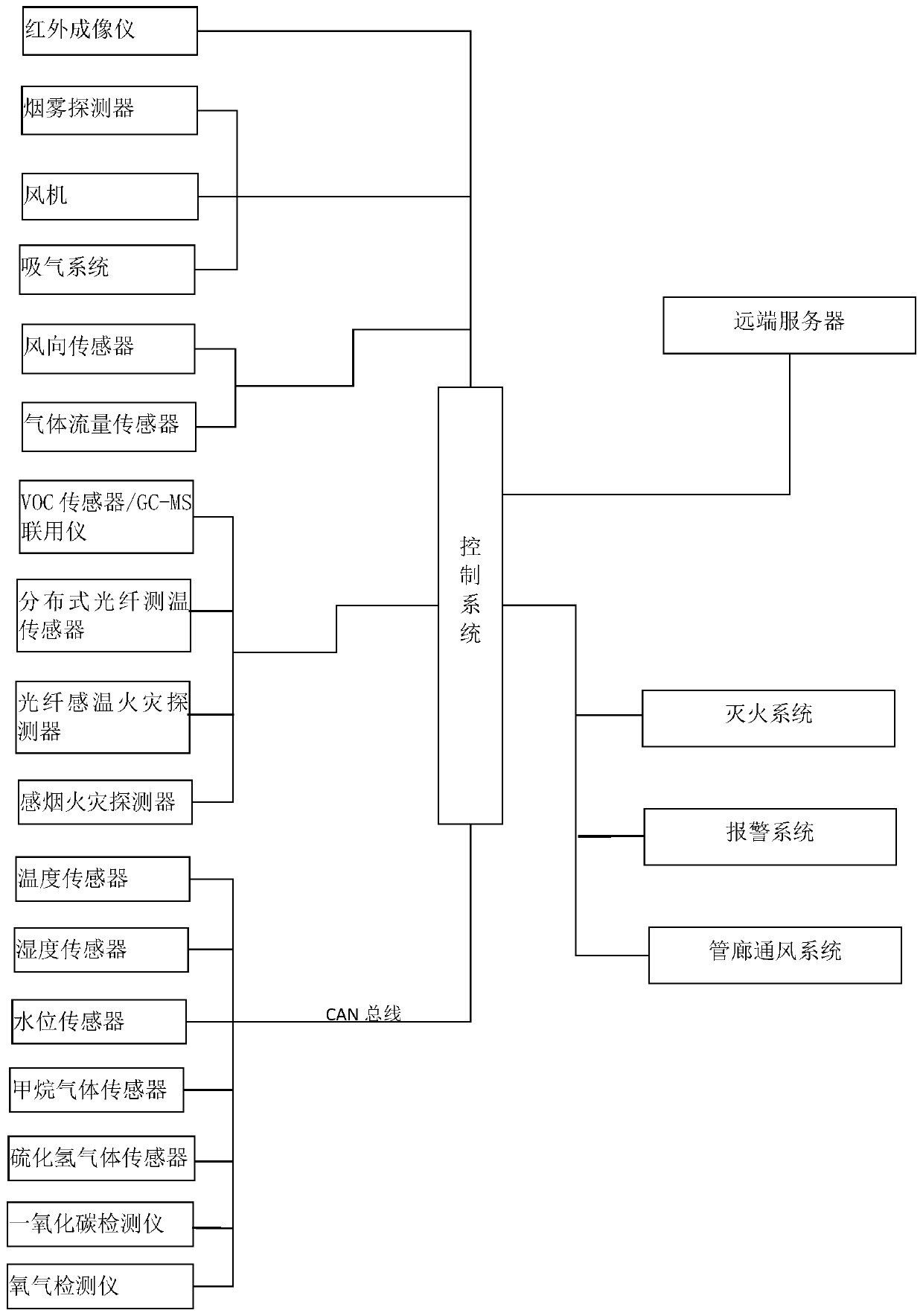
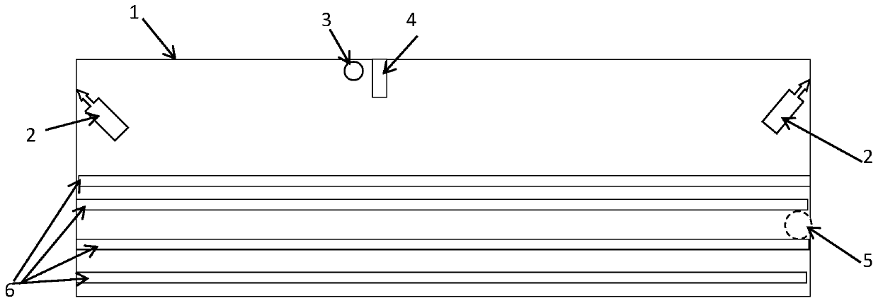
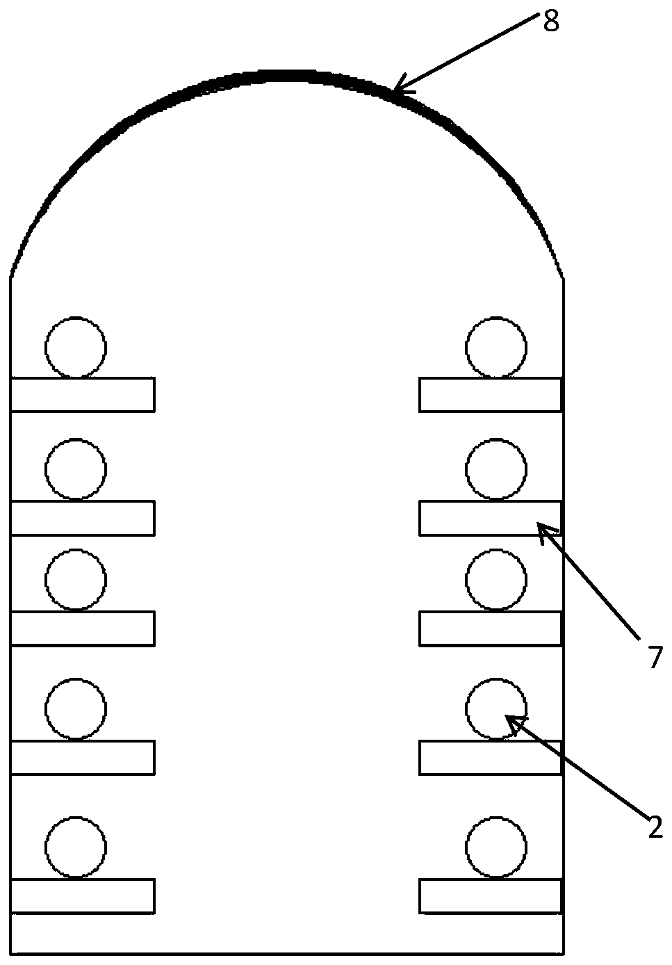
[0031] Such as Figure 1-4 As shown, an intelligent online monitoring system for a pipe gallery includes a control system, a surface temperature sensing device and an active smoke sensing device; the surface temperature sensing device and the active smoke sensing device are electrically connected to the control system and / or communication connection;

[0032] Wherein the surface te...


PUM


Abstract

The invention discloses an intelligent on-line monitoring system for a pipe gallery comprising a surface temperature sensing device which comprises an infrared imager and / or an ultraviolet spectrum monitor and is used for collecting temperature field distribution information in the pipe gallery. The invention also comprises an active smoke sensing device comprises a smoke detector, a fan and an air suction system, the fan is used for increasing airflow power in the pipe gallery, the air suction system is used for sucking airflow to flow to the smoke detector, and the smoke detector senses smoke concentration information in the airflow. The invention further comprises a control system used for receiving the temperature distribution information and the smoke concentration information for data processing and sending a control signal to the surface type temperature sensing device and the active smoke sensing device;The monitoring system is especially suitable for monitoring the cable underground pipe gallery, and is also suitable for monitoring the comprehensive pipe gallery comprising cable facilities. The system is comprehensive in monitoring parameters, strong in alarm condition monitoring capability, high in sensitivity and beneficial to safe, stable and reliable operation of underground pipe gallery facilities.

Description

technical field [0001] The invention relates to the technical field of pipe gallery monitoring, in particular to an intelligent online monitoring system for pipe gallery. Background technique [0002] The power pipe gallery is a tunnel specially built in the underground space of the urban road for the transmission of electricity by power cables. It can also form a comprehensive pipe gallery with natural gas, communication and other equipment; the short corridor is several kilometers, and the length is tens or hundreds of kilometers. It is impossible for inspection personnel to fully grasp the operating conditions in the utility gallery in real time, so its safe operation status, fault status, and environmental status of the operation and maintenance personnel are the top priorities in the utility gallery management environment, but the existing technology In the application of the above purpose, there are still some defects. [0003] For example, the current power utility g...

Claims


Application Information

Patent Timeline
IPC IPC(8): G08B17/10G08B17/06G08B17/12G01D21/02
CPCG01D21/02G08B17/06G08B17/10G08B17/12
Inventor 詹姆斯·刘
Owner 北京泓业致联科技有限公司
Learn More