Cell separation mechanism and device

A separation mechanism and separation device technology, applied in biochemical cleaning devices, enzymology/microbiology devices, biomass post-processing, etc., can solve the problems of inaccurate absorption, low extraction efficiency, cumbersome steps, etc., to improve efficiency and Success rate, lower production cost, the effect of huge market value

Pending Publication Date: 2020-05-29
XIANGYA HOSPITAL CENT SOUTH UNIV
View PDF0 Cites 2 Cited by
  • Summary
  • Abstract
  • Description
  • Claims
  • Application Information

AI Technical Summary

Problems solved by technology

[0005] The manual sample addition process before centrifugation is cumbersome, which may cause PBMC stratification failure or low extraction efficiency due to artificial unstable factors such as liquid surface mixing and erythrocyte sedimentation. When the blood sample volume is large, the manual sample addition takes longer. The greater the error rate;
[0006] After centrifugation, the manual process of taking out the mobile test tube and gently placing it on the PBMC layer is still cautious. The suction is very inaccurate under the naked eye, which often leads to a large loss of cells and the inclusion of impurities such as platelets.
[0007] Usually, it takes an entire morning for the experimenter to get the blood sample and isolate the PBMC, and then it takes a whole day to do flow cytometry or magnetic bead sorting or even primary culture in the downstream. The tedious and delicate steps lead to fatigue and stress. Greatly reduce the success rate and stability of the experiment

Method used


Image

  • Cell separation mechanism and device
  • Cell separation mechanism and device
  • Cell separation mechanism and device

Examples


Embodiment 1

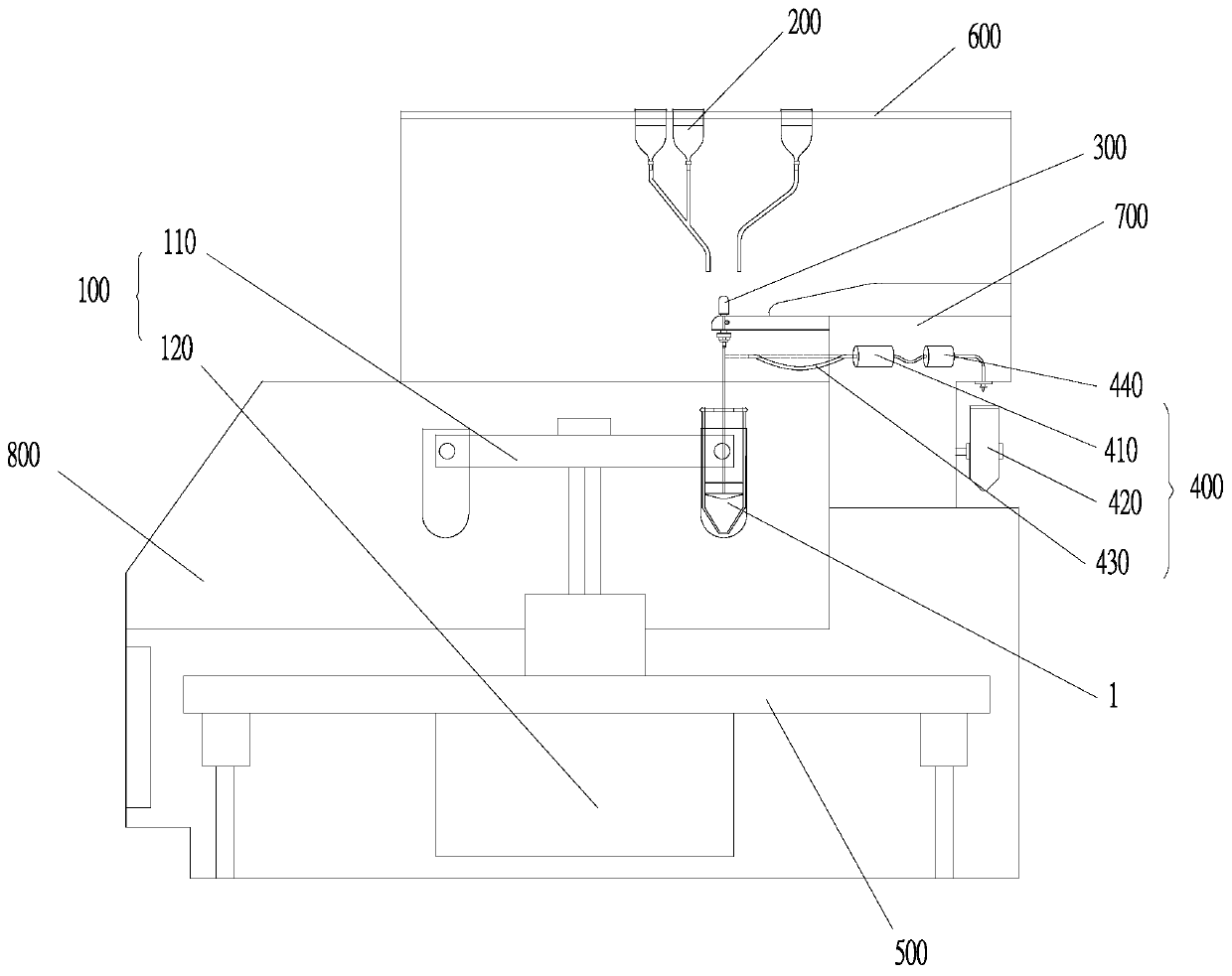
[0040] like figure 1 As shown, the cell separation device of this embodiment is used for automatic batch separation of peripheral blood PBMCs, which includes a centrifugal mechanism 100 , a drug adding mechanism 200 , a cell separation mechanism, a suction mechanism 400 and a controller 800 .

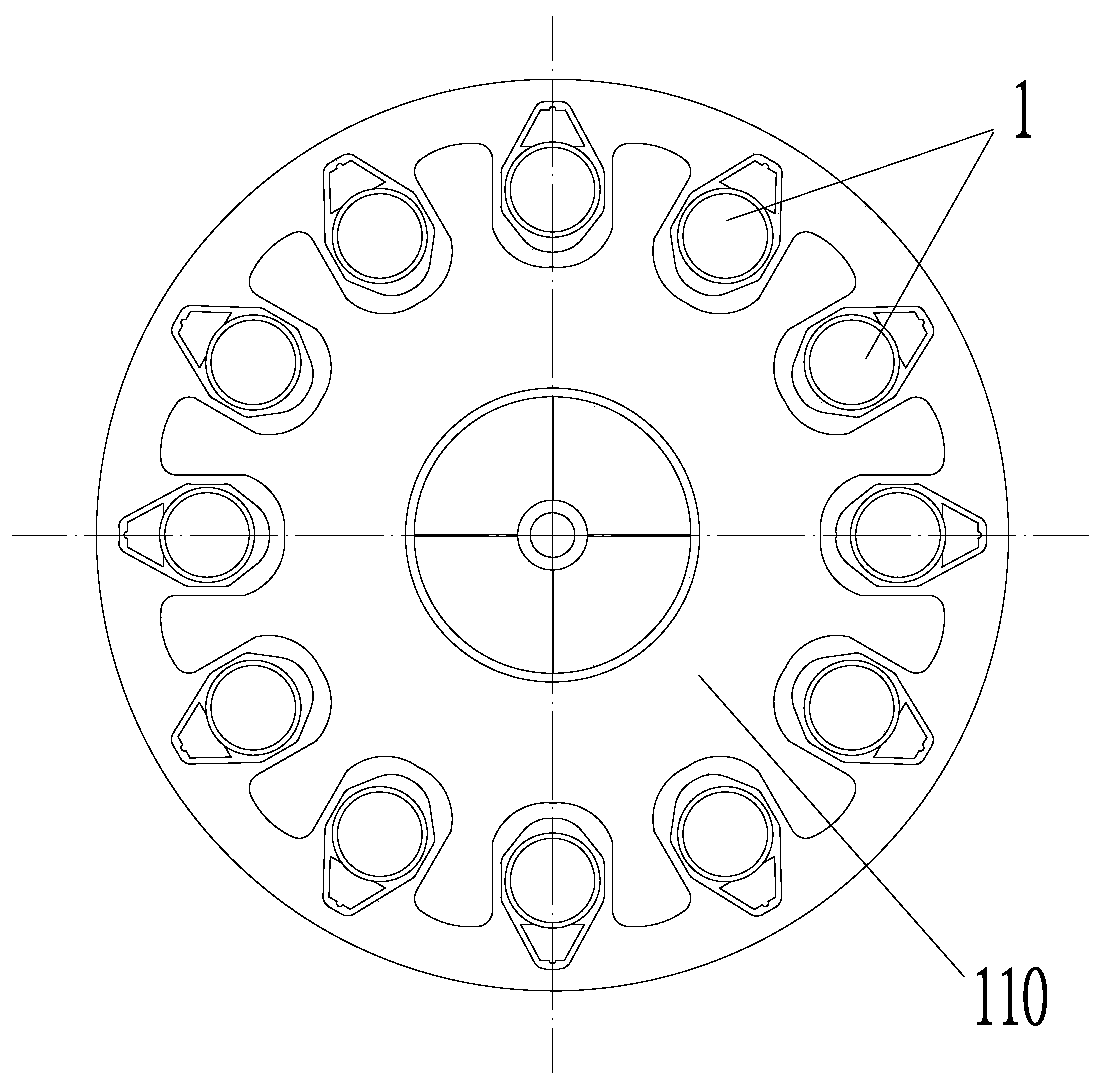
[0041] The centrifugal mechanism 100 includes a centrifugal frame 110 and a centrifugal motor 120 that drives the centrifugal frame 110 to rotate. The centrifugal frame 110 is supported on the foundation or the test platform by the first support 500. The centrifugal motor 120 is installed below the first support 500 and can drive the centrifugal The frame 110 rotates circumferentially. like figure 2 As shown, the centrifugal frame 110 is provided with a plurality of centrifugal stations, and the plurality of centrifugal stations are distributed on a circle whose center is the geometric center of the upper surface of the centrifugal frame 110 .

[0042]The dosing mechanism 200 is susp...


PUM


Abstract

The invention discloses a cell separation mechanism and device. The separation mechanism comprises a separating pipe and a separating rod, wherein the separating rod can do axial motion and can be circumferentially rotated; a plurality of partitioning plates which are arranged at intervals in the axial direction are fixed to the inner wall of the separating pipe; first through holes are formed inthe partitioning plates; baffle plates are mounted on the partitioning plates; the partitioning plates are coaxial to the baffle plates and the baffle plates can be axially rotated relative to the partitioning plates; a plurality of latch fasteners corresponding to the baffle plates are arranged on the separating rod; second through holes through which all the latch fasteners pass are formed in the partitioning plates and the baffle plates; locking holes matched with the corresponding latch fasteners are formed by the second through holes in the baffle plates; and after the latch fasteners areinserted into the corresponding locking holes, the corresponding baffle plates can be driven by circumferential rotation of the separating rod to be rotated so as to turn on or turn off the corresponding first through holes. Therefore, only by providing axial and rotational power for the separating rod, isolation of liquid after addition of each kind of liquid required by cell separation can be controlled before separation, and each layer of liquid is isolated after separation, so that a pumping device can conveniently and automatically pump a target layer, and thus, suction of other layers of liquid impurities is avoided.

Description

technical field [0001] The invention belongs to the technical field of biomedical equipment, and in particular relates to a cell separation mechanism and device. Background technique [0002] Preparation of autologous CART for Chimeric Antigen Receptor Immune Cell Therapy (CAR): Obtain fresh whole blood samples from patients, and obtain sorted patient white blood cells (WBCs) by removing red blood cells, separating platelets and washing. Then, the T cells are activated, transduced with the CAR gene, expanded to a certain number, filled and sealed for treatment. After certain quality control, the patient is pretreated, and the CART cells are injected into the patient. [0003] PBMC cell preparation: Peripheral blood mononuclear cells (PBMC) mainly refer to lymphocytes and monocytes. The separation of PBMC is a basic technique in immunology research. PBMCs have a different density than other blood components. Therefore, when using the ficoll-hypaque mixed solution with a sp...

Claims


Application Information

Patent Timeline
Patent Type & Authority Applications(China)
IPC IPC(8): C12M1/00C12M1/24C12M1/26
CPCC12M23/08C12M23/34C12M33/04C12M45/04
Inventor 邱元正陆兆屹李果王治国邓小丽刘勇刘超王芸芸卢善翃
Owner XIANGYA HOSPITAL CENT SOUTH UNIV
Why Eureka
Try Eureka