
Transparent electrode potential real-time monitoring device and method based on oblique incident light reflection difference method

A real-time monitoring, electrode potential technology, applied in the direction of measurement device, polarization influence characteristics, material electrochemical variables, etc., can solve the problems of inaccurate monitoring, electrode damage, electrical measurement method relying on electronic connection, etc., to achieve the effect of accurate monitoring

Inactive Publication Date: 2020-05-29
SOUTHWEST UNIVERSITY
View PDF1 Cites 1 Cited by
  • Summary
  • Abstract
  • Description
  • Claims
  • Application Information

AI Technical Summary

Problems solved by technology

Existing optical technologies, including electrochemiluminescence and surface plasmon resonance imaging microscopy, have their own obvious limitations; electrical measurement methods rely on electronic connections, and it is difficult to perform spatially resolved measurement (imaging) of the electrode potential on the entire electrode surface. Not applicable when wireless remote measurements are required
[0003] When the existing potential state of the electrode is detected, it is generally carried out by contacting or electrically connecting the electrode surface. However, this detection method will have a certain impact on the electrode surface itself, resulting in inaccurate monitoring, or to electrode damage

Method used


Image

  • Transparent electrode potential real-time monitoring device and method based on oblique incident light reflection difference method
  • Transparent electrode potential real-time monitoring device and method based on oblique incident light reflection difference method
  • Transparent electrode potential real-time monitoring device and method based on oblique incident light reflection difference method

Examples


Embodiment 1

[0043] Oblique incident light reflectance difference method (OIRD) is a new method developed in the past two decades to detect interface changes without marking, without damage, and in real time. By measuring the two polarized light components of the reflected light obliquely incident on the interface Changes in the difference between (s and p) are used to detect changes in interface characteristics. Subtle changes in dielectric constant or scale in space and time caused by composition changes and structural changes on the interface can cause incident light s and Different changes in the reflectivity of the p-component to obtain the OIRD signal.

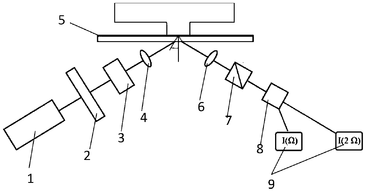
[0044] Such as figure 1 As shown, in which, 1 in the figure represents the laser, 2 represents the photoelastic modulator PEM, 3 represents the phase shifter PS, 4 represents the incident lens L1, 5 represents the transparent electrode, 6 represents the exit lens L2, and 7 represents the polarization analyzer , 8 represents the phot...

Embodiment 2

[0083] The method for real-time monitoring of the transparent electrode potential based on the oblique incident light reflection difference method provided in this embodiment includes the following steps:

[0084] The laser emits a beam of elliptically polarized light;

[0085] The polarized light passes through the phase shifter after being modulated by the photoelastic modulator;

[0086] The light emitted from the phase shifter is focused by the incident lens and obliquely incident on the surface of the transparent electrode according to the preset incident angle;

[0087] The laser light reflected from the electrode surface enters the polarization analyzer after passing through the exit lens;

[0088] The light emitted from the polarization analyzer is converted into a voltage signal through a photodiode;

[0089] The fundamental frequency component signal and the multiplier frequency component signal of the modulation frequency in the voltage signal are collected by two...

Embodiment 3

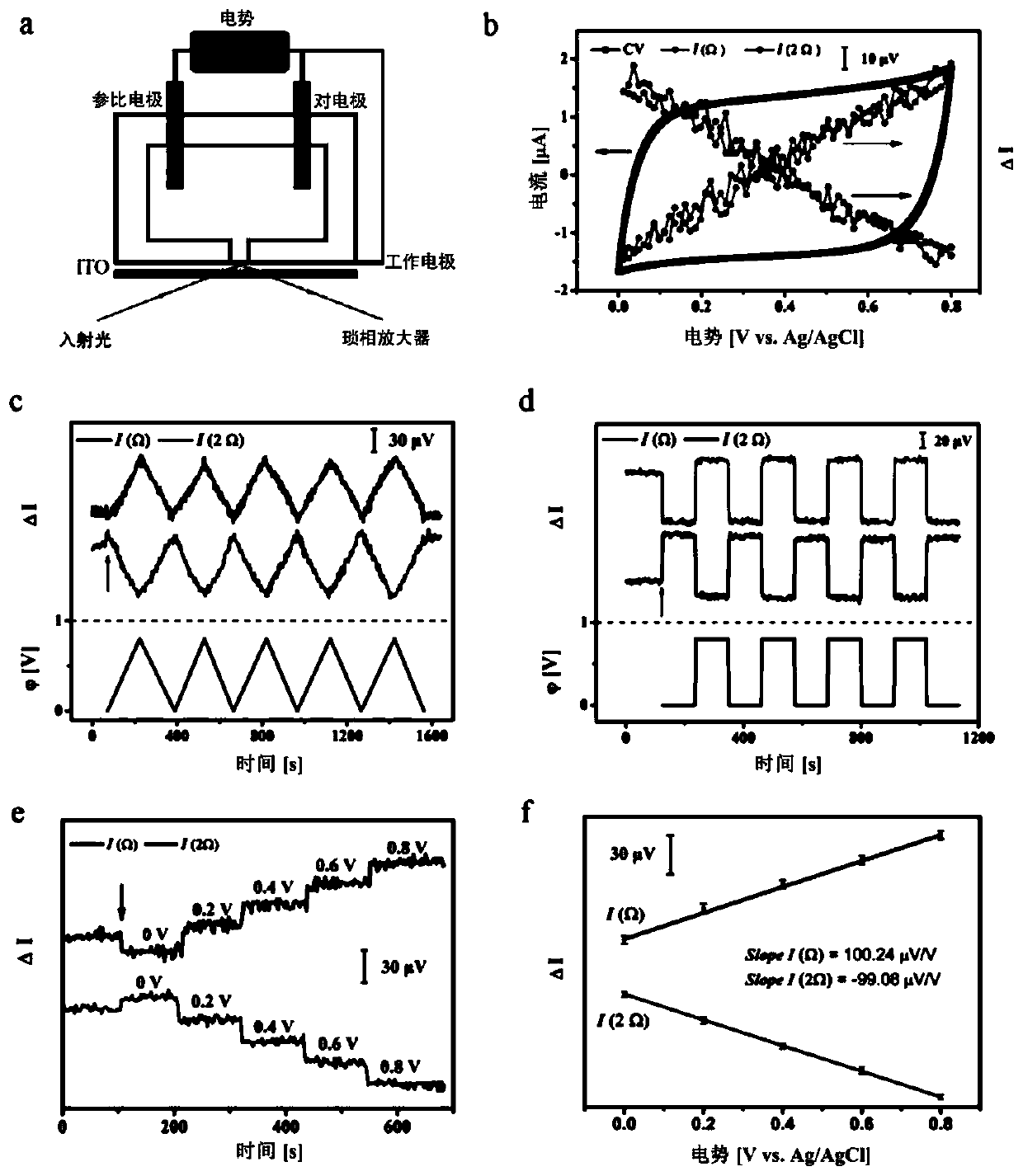
[0095] Such as figure 22a) shows the scheme of the OIRD setup for monitoring potential changes in a three-electrode system; 2b) ITO-1 electrode in 3M KCl solution at a scan rate of 5mV s-1 from 0V to 0.8V The CV curve and the simultaneous OIRD signal were recorded above; the OIRD signal was recorded simultaneously; 2c) at a scan rate of 5 mV s-1 during 5 consecutive potential cycles from 0 to 0.8V; 2d) the potential from 0 to 0.8V Steps; 2e) Potentials were stepped from 0 to 0.8 V at 0.2 V intervals; 2f) The average OIRD signal for each potential was plotted against the applied potential in 2e) and the corresponding linear fit line.

[0096] The three-electrode system provided in this embodiment is provided with a scanning system for real-time adjustment of the driving voltage of the electrodes.

[0097] What this embodiment provides is to monitor the potential change of the ITO electrode surface in real time, and the specific process is as follows:

[0098] Under the tradi...


PUM

PropertyMeasurementUnit
Wavelengthaaaaaaaaaa
Thicknessaaaaaaaaaa
Thicknessaaaaaaaaaa

Abstract

The invention discloses an electrode potential real-time monitoring device based on an oblique incident light reflection difference method. The device comprises a laser which is used for emitting a beam of elliptically polarized light, the polarized light sequentially passes through a photoelastic modulator and a phase shifter, and then is obliquely incident to a surface of a transparent electrodethrough an incident lens according to a preset incident angle, the reflected light returned from the surface of the transparent electrode passes through a polarization analyzer and then is convertedinto a voltage signal through a photodiode, and two lock-in amplifiers collect a fundamental frequency component signal and a frequency multiplication component signal of the modulation frequency in voltage signals and input the signals to a processor for processing. The device is advantaged in that the electrode potential of a transparent electrode\solution interface is monitored in real time byutilizing the oblique incident light reflection difference technology, change of the electrode potential is directly monitored in situ in real time, potential distribution of the whole electrode surface can be detected and imaged in a scanning mode, and a novel method is provided for space-time resolution measurement of the electrode surface potential.

Description

technical field [0001] The invention relates to the technical field of electrochemical analysis and testing, in particular to a transparent electrode potential real-time monitoring device and method based on oblique incident light reflection difference method. Background technique [0002] Measuring the electrode potential at the electrode / solution interface is of great significance for the study of surface electrochemical phenomena and related nanoscience, energy research, and bioelectrochemistry, among others. At present, there are many methods for detecting electrode potential, which are mainly divided into electrical and optical techniques. Existing optical technologies, including electrochemiluminescence and surface plasmon resonance imaging microscopy, have their own obvious limitations; electrical measurement methods rely on electronic connections, and it is difficult to perform spatially resolved measurement (imaging) of the electrode potential on the entire electrod...

Claims


Application Information

Patent Timeline
IPC IPC(8): G01N27/48G01N21/21
CPCG01N21/211G01N27/48
Inventor 胡卫华李玲
Owner SOUTHWEST UNIVERSITY
Learn More