Non-split complete matching layer absorption boundary method

A completely matched layer and absorption boundary technology, applied in the field of seismic exploration, can solve problems such as difficulty in absorbing large-angle incident waves with stability, unfavorable promotion of seismic wave simulation, and large memory occupation. The effect of taking up less space

Active Publication Date: 2020-05-29
JILIN UNIV
View PDF4 Cites 4 Cited by
  • Summary
  • Abstract
  • Description
  • Claims
  • Application Information

AI Technical Summary

Problems solved by technology

The splitting method takes up a lot of memory and has low computational efficiency. Compared with the equation transformation, the wave field transformation has a form that does not change the wave equation, which is more conducive to the realization and promotion of the boundary. However, the current method for the wave field transforma...

Method used


Image

  • Non-split complete matching layer absorption boundary method
  • Non-split complete matching layer absorption boundary method
  • Non-split complete matching layer absorption boundary method

Examples


Embodiment 1

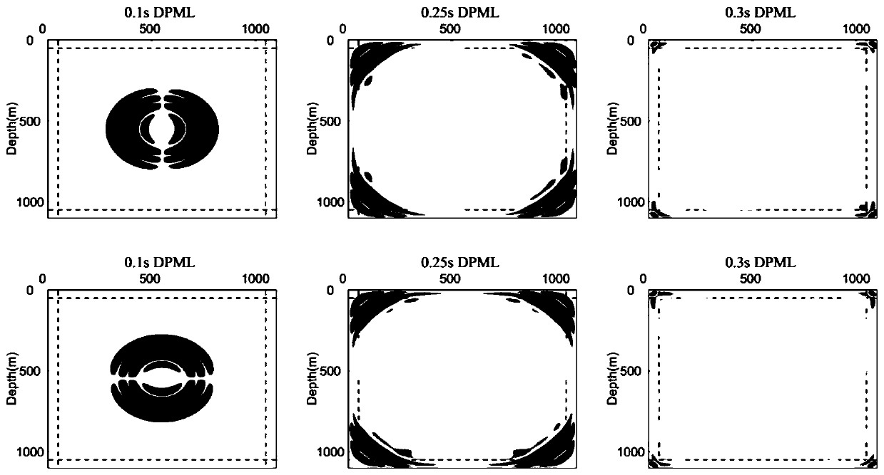
[0109] According to the exploration requirements, two common source distributions are established. Various boundary conditions and attenuation functions are applied to the numerical simulation of seismic waves, the selected time step is 0.5ms, the loading source is the Reker wavelet, and the main frequency is 25HZ. Establish a model to study the situation of normal incidence of seismic waves. The model size is 1100×1100m (including boundary thickness), and the grid step size is 5m in both x and z directions. The number of PML layers is set to 10, and R is set to 10 -6 , γ is 0.001, φ and δ are 1 and 0.029 respectively, n is 2, and the seismic source is loaded at x=550m, z=550m. The longitudinal wave velocity is 3000m / s, the shear wave velocity is 1400m / s, and the density is 2000Kg / m3.

[0110] Forward results such as Figure 2-Figure 3b shown in figure 2 The snapshots of the wave field simulation at different times are given in , recording the propagation process of seis...

Embodiment 2

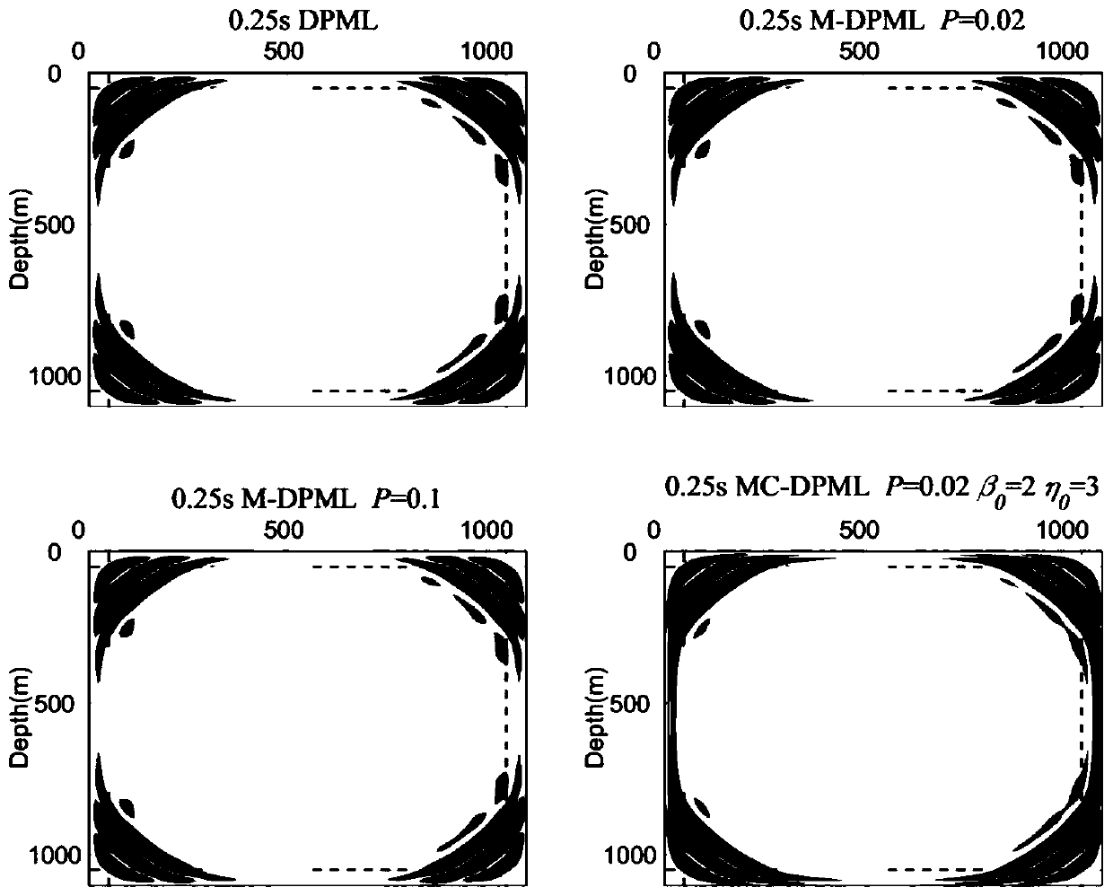
[0112] Conventional incidence is simulated in Embodiment 1, and now a case of approximately parallel incidence is designed. The selected time step is 0.5ms, the loading source is the Reckel wavelet, and the main frequency is 25HZ. Build a model to study the situation of seismic waves incident at large angles. The model size is 2600×1100m (including boundary thickness), and the grid step size is 5m in both x and z directions. The number of PML layers is set to 10, and R is set to 10 -6 , γ is 0.001, φ and δ are 1 and 0.029 respectively, n is 2, and the seismic source is loaded at x=1050m, z=55m. The longitudinal wave velocity is 3000m / s, the shear wave velocity is 1400m / s, and the density is 2000Kg / m3.

[0113] Simulation results such as Figure 4 and shown in Figure 5. When near-parallel incidence occurs, the residual perfectly matched layer produces energy accumulation at the upper boundary, causing false reflections and instability. Such as Figure 5a As shown, when a...


PUM


Abstract

The invention relates to a non-split complete matching layer absorption boundary method, a lower medium is semi-infinite, and a calculation space is limited such that an absorption boundary needs to be introduced when seismic wave propagation is simulated. The absorption boundary does not truly exist in an underground medium, reflection is not formed when actual seismic waves are transmitted to the absorption boundary, and certain false reflection can be brought by artificial boundaries. By adopting a residual error complete matching layer provided by the invention, incident waves can be effectively absorbed, and seismic waves are prevented from being transmitted back to a main area. According to the method, the form of an original equation is not changed, programming implementation is facilitated, and the method can be popularized to more complex medium simulation; an auxiliary equation eliminates a time partial derivative term of an original variable, and the popularization to high-precision forward modeling is more facilitated. Meanwhile, complex frequency shift transformation is successfully realized on the basis of the residual error complete matching layer such that grazing-in waves can be absorbed, and the generation of low-frequency singular values is avoided; and a complete matching layer structure with double attenuation sections is adopted such that the stability isimproved.

Description

technical field [0001] The invention belongs to the technical field of seismic exploration, and in particular relates to an absorbing boundary in the time domain, in particular to a non-split perfectly matching layer absorbing boundary method for realizing wave field transformation by calculating residuals. Background technique [0002] In order to meet the needs of seismic wave forward and inversion, the study of boundary conditions has attracted great attention. Currently, the most widely used boundary conditions are perfectly matched layers (Perfectly matched layers, PML) proposed by Berenger when studying Maxwell's equations. Chew et al. and Collino et al. interpreted it as the result of a complex coordinate stretching transformation. When the incident wave angle is large, the attenuation coefficient will become very small, so the conventional perfectly matched layer cannot absorb the large-angle incident wave, and will produce singular values ​​at extremely low frequen...

Claims


Application Information

Patent Timeline
IPC IPC(8): G01V1/30
CPCG01V1/306G01V2210/62
Inventor 罗玉钦刘财
Owner JILIN UNIV
Why Eureka
Try Eureka