
Punching die

A technology for stamping dies and bottom plates, applied in the field of stamping dies, can solve the problems of inconvenient processing of parts, reduce work efficiency, and increase production costs, and achieve the effects of reducing production costs, improving work efficiency, and increasing production volume.

Inactive Publication Date: 2020-06-02
淮北德林机械设备有限公司
View PDF15 Cites 9 Cited by
  • Summary
  • Abstract
  • Description
  • Claims
  • Application Information

AI Technical Summary

Problems solved by technology

However, in the process of use, when the stamping die head fails, it is not convenient to replace the stamping die head, which reduces the work efficiency and affects the production of parts, resulting in increased production costs and great inconvenience to the processing of parts

Method used


Image

  • Punching die
  • Punching die
  • Punching die

Examples


Embodiment 1

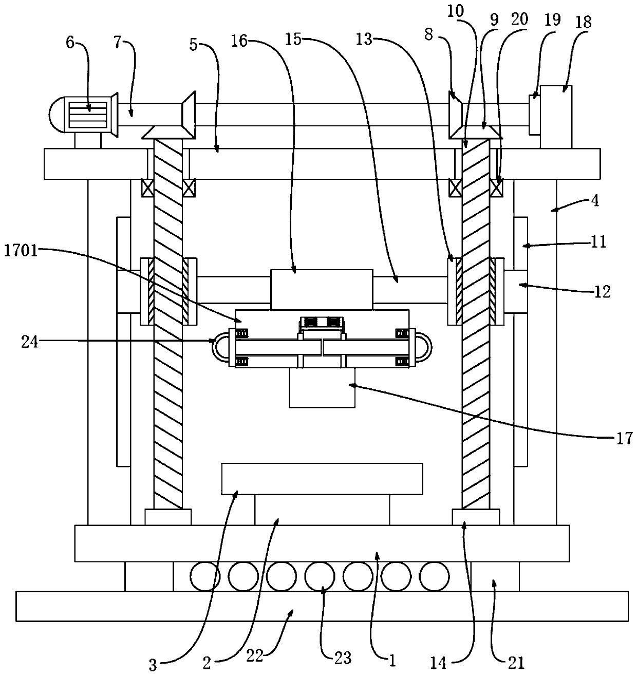
[0023] Put the workpiece on the top of the workbench 3, then start the drive motor 6, the drive motor 6 drives the drive shaft 7 to rotate, the drive shaft 7 drives the first gear 8 to rotate, the first gear 8 drives the second gear 9 to rotate, the second gear 9 Drive the threaded shaft 10 to rotate, because the threaded shaft 10 is threadedly connected with the threaded sleeve 13, and the threaded sleeve 13 is limited by the first slider 12 and the first chute 11, so that the threaded sleeve 13 moves downward on the surface of the threaded shaft 10 , the threaded sleeve 13 drives the stamping die head device 17 to move downward through the sliding rod 15 and the fixing seat 16, so that the stamping head 1702 moves downward to process the workpiece.

Embodiment 2

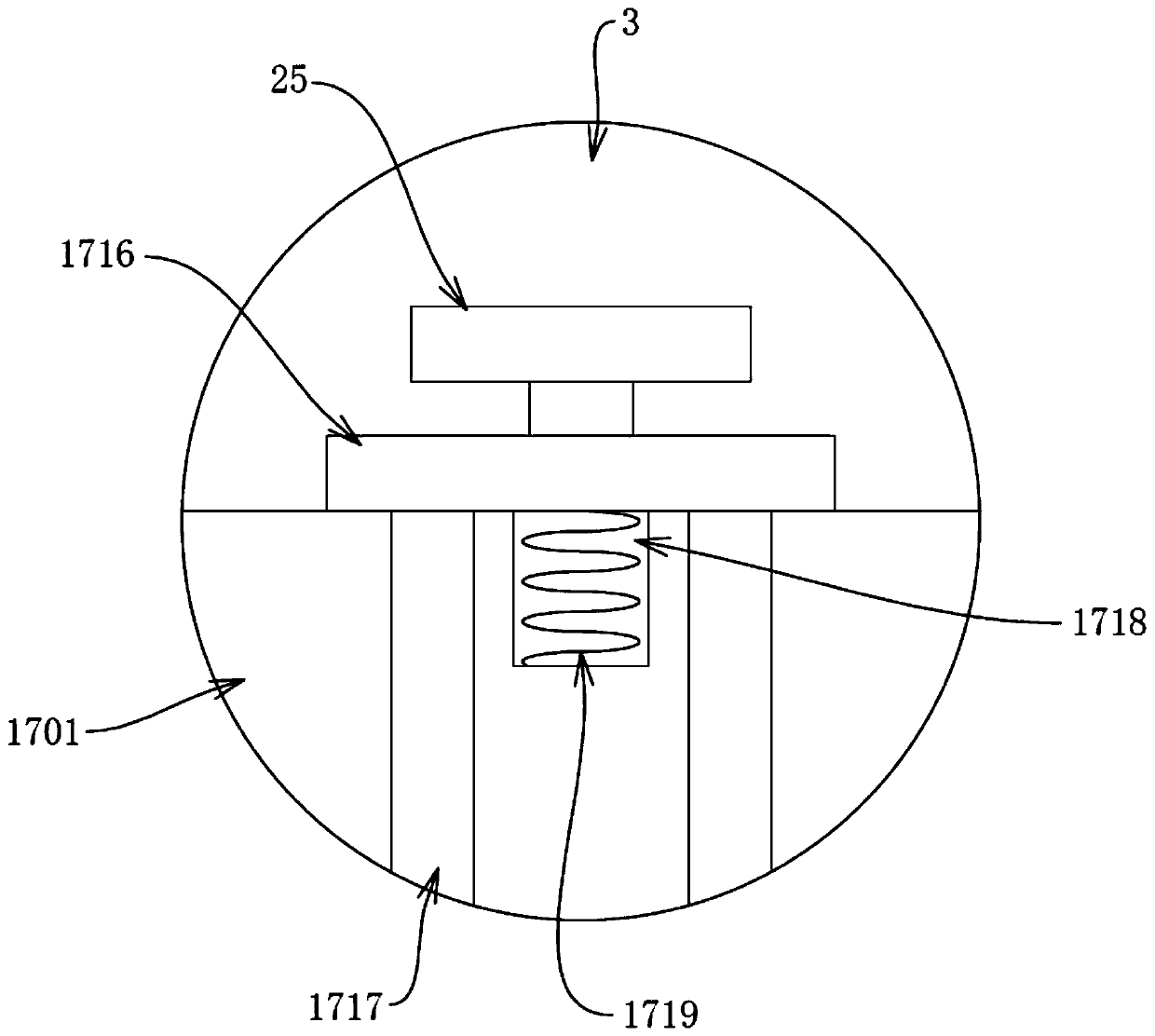
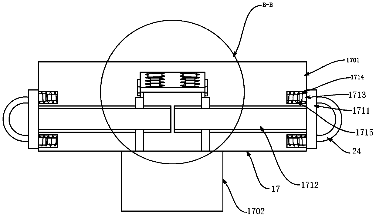
[0025] When the stamping head 1702 breaks down, the second handle 25 drives the clamping block 1716 to move backward, so that the clamping rod 1717 is disengaged from the support block 1710, the third spring 1719 is in a stretched state, and then pulled by the first handle 24 The block 1711 moves to both sides, and the pulling block 1711 drives the second telescopic rod 1713 and the second spring 1715 to move to both sides, the second telescopic rod 1713 and the second spring 1715 are in a stretched state, and the pulling block 1711 drives the stop block 1712 to Move on both sides, so that the limit block 1712 and the support block 1710 are separated from each other. Since the first telescopic rod 1708 and the first spring 1709 are in a compressed state, an elastic force is generated on the support block 1710, so that the support block 1710 drives the stamping head 1702 to move downward. The stamping head 1702 and the fixing groove 1703 are separated from each other, and the st...


PUM


Abstract

The invention discloses a punching die. A bottom plate is included. The middle point position of the top of the bottom plate is fixedly connected with a supporting base. The top of the supporting baseis fixedly connected with a workbench. The positions, located on the left side and the right side of the workbench, of the top of the bottom plate are fixedly connected with fixing plates, and the tops of the two fixing plates are fixedly connected through a top plate. Through mutual cooperation of a drive motor, a drive rotation shaft, a first gear, a second gear, a threaded rotation shaft, first sliding grooves, first sliding blocks, threaded sleeves, first bearings, a sliding rod, a fixing base and a punching die head device, the problem that according to a common mechatronics punching die, punching die head replacement is not convenient is solved; and a clamping connection manner is adopted, when a punching die head breaks down, the punching die head is conveniently replaced, the workefficiency is improved, the component production capacity is increased, accordingly, the production cost is reduced, and great convenience is brought to component machining work.

Description

technical field [0001] The invention relates to the technical field of mechatronics, in particular to a stamping die. Background technique [0002] Stamping die is a special process equipment for processing materials into parts or semi-finished products in cold stamping processing, called cold stamping die. Stamping is a pressure processing method that uses a mold installed on a press to apply pressure to the material at room temperature to cause separation or plastic deformation to obtain the required parts. A mold is a tool used to shape an article. This tool is composed of various parts. Different molds are composed of different parts. It mainly realizes the processing of the shape of the article through the change of the physical state of the formed material. It is used under the action of external force in blanking, forming stamping, die forging, cold heading, extrusion, pressing of powder metallurgy parts, die casting, and compression molding or injection molding of e...

Claims


Application Information

Patent Timeline
IPC IPC(8): B21D37/10
CPCB21D37/10
Inventor 吴义成
Owner 淮北德林机械设备有限公司
Learn More