
A signal processing method and device for a novel ultra-high precision fiber optic gyroscope

A signal processing device, fiber optic gyroscope technology, applied in Sagnac effect gyroscopes, measuring devices, instruments and other directions, to achieve the effect of suppressing influence, eliminating influence and improving possibility

Active Publication Date: 2020-12-15
BEIHANG UNIV
View PDF15 Cites 0 Cited by
  • Summary
  • Abstract
  • Description
  • Claims
  • Application Information

AI Technical Summary

Problems solved by technology

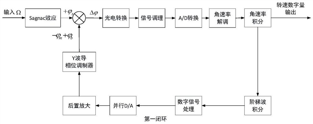
In this process, due to the limitation of the number of bits of the D / A converter, there must be a certain quantization error in the tracking and compensation of the Y waveguide half-wave voltage. In the medium and low precision fiber optic gyroscope, the quantization error does not affect the accuracy of the gyroscope. The main error, however, for ultra / very high-precision fiber optic gyroscopes, the output error caused by any noise and error is extremely obvious, even a small quantization error of magnitude also exists for strategic reference-level ultra-high-precision fiber optic gyroscopes The impact that cannot be ignored, especially the impact on the short-term accuracy of ultra-high precision fiber optic gyroscopes, etc. is very significant

Method used


Image

  • A signal processing method and device for a novel ultra-high precision fiber optic gyroscope
  • A signal processing method and device for a novel ultra-high precision fiber optic gyroscope
  • A signal processing method and device for a novel ultra-high precision fiber optic gyroscope

Examples


Embodiment Construction

[0033] The technical solutions in the embodiments of the present invention will be clearly and completely described below in conjunction with the accompanying drawings in the embodiments of the present invention. Obviously, the described embodiments are only for illustration and are not intended to limit the present invention.

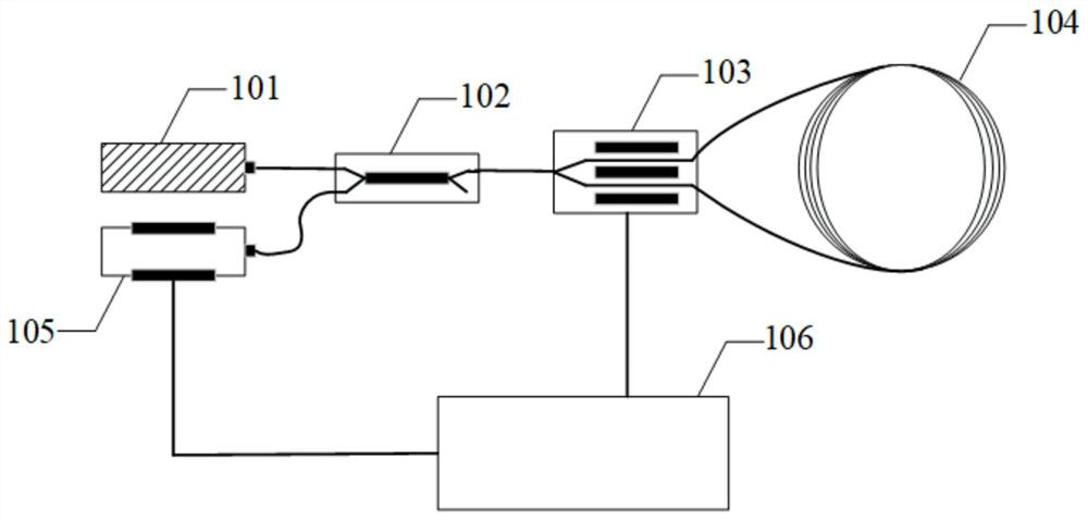
[0034]The fiber optic gyroscope is an angular rate sensitive device. The light source emits a light beam, which is divided into two beams of light with the same phase and opposite propagation directions after passing through the coupler and the phase modulator. If the fiber optic ring rotates, due to the Sagnac effect, the forward / reverse After the two beams of light propagate in the fiber ring, there will be a phase difference, and the light intensity will change when they interfere at the coupler. The photodetector converts the light signal into a voltage signal, and demodulates and detects the light intensity change in the signal processing module. ,...


PUM


Abstract

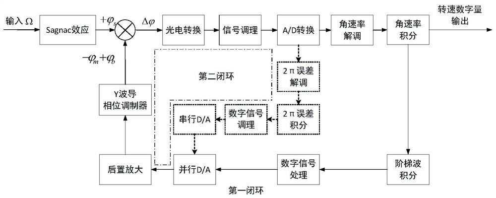
The invention discloses a signal processing method and device of a novel ultrahigh-precision fiber-optic gyroscope. On the basis of a traditional double-closed-loop feedback scheme, a compensation mode of the 2pi error is changed, an error detection-closed loop compensation mode is changed into a real-time monitoring-division cancellation mode, and a half-wave voltage real-time tracking channel based on division operation is formed, so that the original second closed-loop work can be replaced, the truncation quantization error caused by the limited number of the limited serial D / A converter inthe original second closed-loop can be greatly inhibited, the influence of the quantization error on the ultrahigh-precision fiber-optic gyroscope can be effectively inhibited, and the application possibility of the ultrahigh-precision interference type fiber-optic gyroscope is further improved. Moreover, on the basis of not changing the signal detection process in the full-digital closed-loop scheme of a traditional fiber-optic gyroscope, the use of electronic components is reduced, and the influence of the second closed loop on the fiber-optic gyroscope is eliminated in a simplest manner.

Description

technical field [0001] The invention relates to the technical field of fiber optic gyroscopes, in particular to a signal processing method and device for a novel ultra-high-precision fiber optic gyroscope. Background technique [0002] Due to its high measurement accuracy, good sensitivity, large dynamic range, small size, light weight, long life and easy integration, the fiber optic gyroscope is widely used in military and civilian fields, and plays an important role in missile guidance, satellite navigation and attitude control. In recent years, it has become a research hotspot all over the world. Ultra-high-precision fiber optic gyroscope is the pinnacle of fiber optic gyroscope technology in the world at present. It is mainly used in high-precision ship (boat)-borne inertial navigation systems such as submarines and aircraft carriers, and has great military strategic significance. [0003] Typical interferometric fiber optic gyroscopes, such as figure 1 As shown, it ma...

Claims


Application Information

Patent Timeline
Patent Type & Authority Patents(China)
IPC IPC(8): G01C19/72G01C25/00
CPCG01C19/72G01C25/005
Inventor 王夏霄孔令海张祖琛郑月于佳张春熹
Owner BEIHANG UNIV
Learn More