Pressure sensor calibration device

A technology of pressure sensor and calibration device, which is applied in the direction of measuring device, calibration/testing of force/torque/power measuring instrument, and measurement of fluid pressure. Simple, overcoming oversized effects

Inactive Publication Date: 2020-06-02
ZHONGBEI UNIV
View PDF6 Cites 1 Cited by
  • Summary
  • Abstract
  • Description
  • Claims
  • Application Information

AI Technical Summary

Problems solved by technology

Its structure is simple, easy to use, can overcome the problem that the existing pressure sensor calibration device is too large and difficult to move, and is more suitable for the pressure sensor calibration in the actual experimental place

Method used


Image

  • Pressure sensor calibration device
  • Pressure sensor calibration device
  • Pressure sensor calibration device

Examples


Embodiment Construction

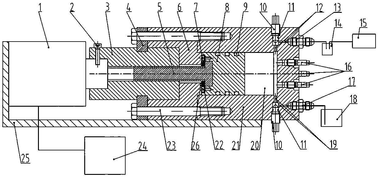
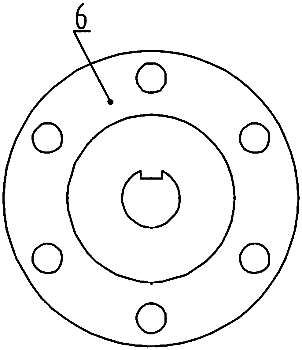
[0022] A pressure sensor calibration device, including a stepping motor 1, a transmission nut 3, a nut limit plate 4, a transmission screw 5, a cylinder head 6, a piston 8, a sealing valve 10, an oil return cylinder 14, a vacuum pump 15, a pressure sensor 16, Fuel tank 18, cavity 21, control box 24.

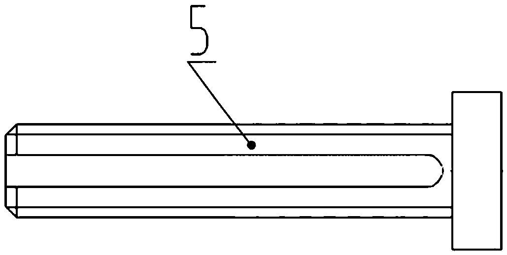
[0023]The drive nut 3 is cylindrical, with an internal thread in its center. The nominal size of the internal thread is consistent with the nominal size of the thread on the drive screw 5, and the two form a helical pair transmission mechanism; the left end of the drive nut 3 has a light hole, the diameter of the light hole and the step The shaft head of the motor 1 has a clearance fit, and the two are rigidly fixed together by the anti-rotation bolt 2 to realize axial and circumferential positioning; the outer cylinder of the drive nut 3 is provided with an annular groove for installing the nut limiter plate 4, and the nut limiter The position plate 4 only limits the axial movem...


PUM


Abstract

The invention provides a pressure sensor calibration device. The pressure sensor calibration device comprises a stepping motor, a transmission nut, a nut limiting plate, a transmission screw, a cylinder cover, a screw limiting plate, a piston, a gas circuit connector, an oil return tank, a vacuum pump, an oil circuit connector, an oil tank, a pressure sensor, a cavity, a control box, a sealing valve and the like. According to the device, the control box is used for controlling the stepping motor to work to drive the screw to rotate, and then the piston is telescopically controlled by the screwto compress the hydraulic oil to generate the pressure signals with different frequencies, amplitudes or pulse widths. The pressure signal is wide in to-be-measured parameter change range and controllable in change speed, is suitable for the calibration of the pressure sensor, and has practicability. The pressure sensor calibration device is simple in design, simple and feasible in operation process and more accurate in calibration result, is capable of solving the problem that an existing pressure sensor calibration device is too large in size and is not easy to move, and is more suitable for the pressure sensor calibration in actual experiment places.

Description

technical field [0001] The invention belongs to the field of non-standard instrument experiment calibration, in particular to a pressure sensor calibration device. Background technique [0002] In the electronic test system, the sensor is at the forefront of the entire test system to sense or respond to the most primitive external information, and convert it into a usable output according to certain rules. Most of the signals to be measured are physical, chemical, biological and other non-electrical signals. It is far more difficult to complete the conversion and transmission of non-electrical signals to electrical signals than the direct conversion and transmission of electrical signals, so sensors are usually the core components of the test system. , is also the weakest link in the whole test system. Whether the sensor can reliably measure the original data will directly affect the accuracy and reliability of the test results, and its importance has long been fully unders...

Claims


Application Information

Patent Timeline
Patent Type & Authority Applications(China)
IPC IPC(8): G01L25/00G01L27/00
CPCG01L25/00G01L27/005
Inventor 张瑜张红艳全鑫李艳辉徐鹏裴乾飞汪阳张嘉铭
Owner ZHONGBEI UNIV
Why Eureka
Try Eureka