Tubular solid oxide fuel cell structure

A solid oxide and fuel cell technology, applied in fuel cells, circuits, electrical components, etc., can solve the problems of poor battery mass transfer performance, temperature and thermal stress, and achieve the goals of avoiding temperature and thermal stress, reducing power consumption, and reducing flow rate Effect

Active Publication Date: 2020-06-02
XI AN JIAOTONG UNIV
View PDF14 Cites 9 Cited by
  • Summary
  • Abstract
  • Description
  • Claims
  • Application Information

AI Technical Summary

Problems solved by technology

[0005] In order to solve the problem of poor battery mass transfer performance and local temperature and thermal stress caused by direct internal reforming in the existing tubular SOFC technology, the present invention provides a new tubular so

Method used


Image

  • Tubular solid oxide fuel cell structure
  • Tubular solid oxide fuel cell structure
  • Tubular solid oxide fuel cell structure

Examples


Embodiment 1

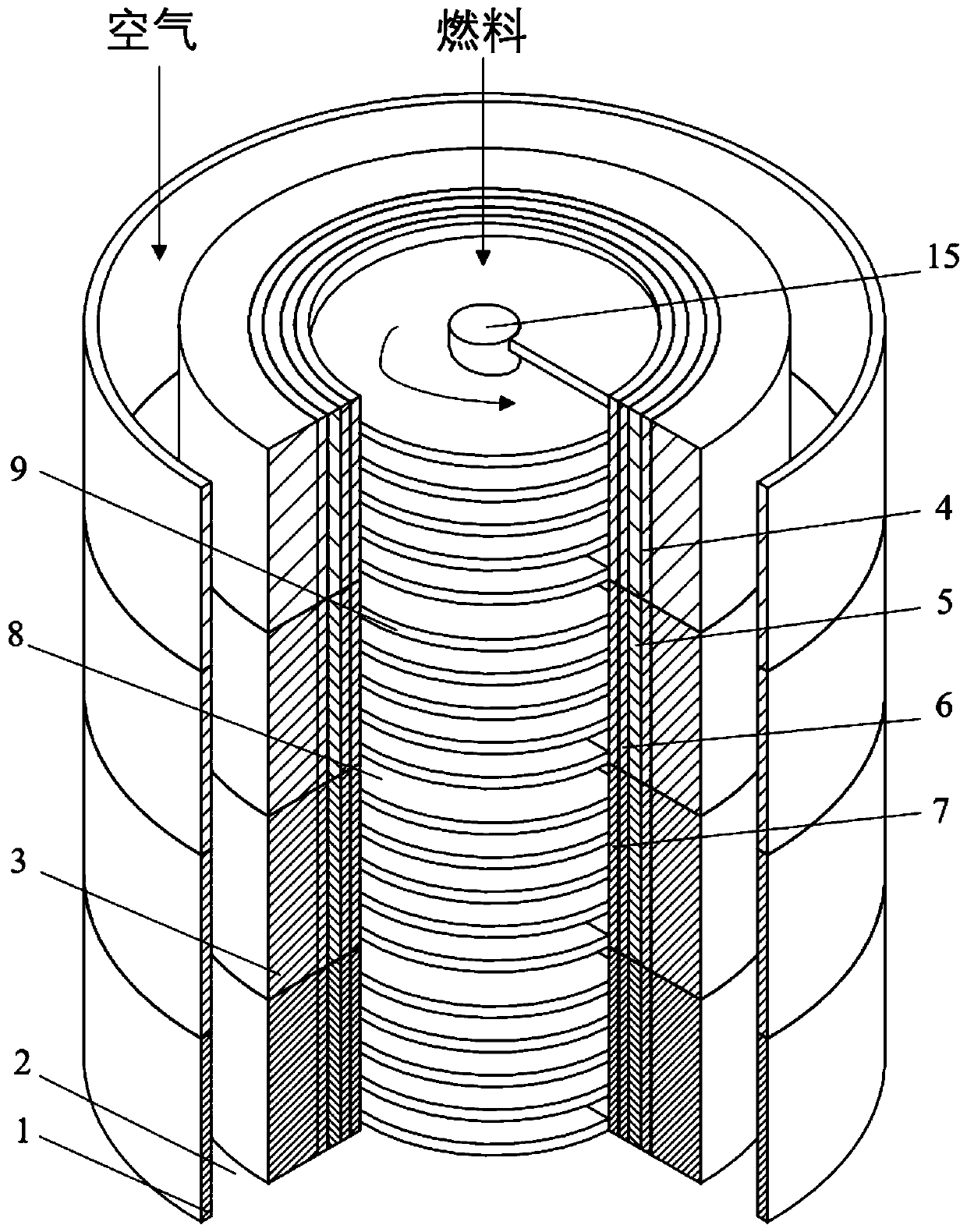
[0044] like Figure 1 to Figure 6As shown, a tubular solid oxide fuel cell structure of the present invention uses high-temperature methane reformed gas as fuel, at least the cathode, anode and electrolyte structure, and the anode gas formed by the outermost shell structure and the anode electrode support layer Channel 2, into which high-temperature reforming gas is introduced; the innermost axis channel is cathode gas channel 8, wherein air is introduced into; the reaction gas in the cathode and anode gas channels 2 is introduced through the cathode and anode electrode support layer 3 The reaction area where the conversion of chemical energy into electrical energy takes place.

[0045] Its outermost shell should have good heat insulation, or its outermost shell should be covered by a material with good heat insulation. The anode, cathode and electrolyte layer 5 should have good heat resistance. The electrode support layer is porous to ensure that the reaction gas can reach ...

Embodiment 2

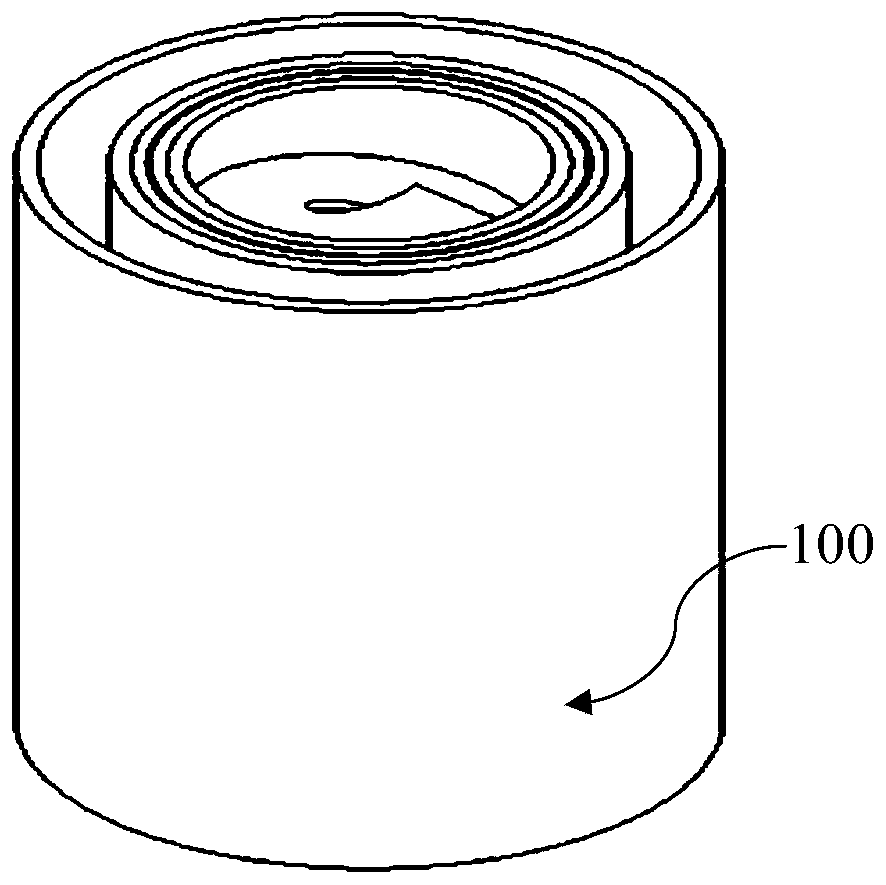
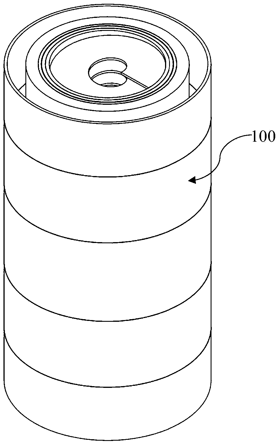
[0052] figure 2 It is a structural schematic diagram of the SOFC unit of the present invention.

[0053] figure 1 It is a cross-sectional view of a quarter of an example of an axially bisected tubular SOFC of the present invention.

[0054] image 3 and Figure 4 It is a three-dimensional schematic diagram and a full cross-sectional view of an example of axial unequal division of the tubular SOFC of the present invention.

[0055] The SOFC involved in the present invention has a tubular structure, and the anode and cathode of the battery are respectively arranged outside and inside the circular tube. The layers from the outside to the inside along the radius of the circular tube are: battery casing 1, anode gas channel 2, anode electrode support layer 3, anode reaction layer 4, electrolyte layer 5, cathode reaction layer 6, cathode support layer 7, Cathode gas channel 8, spiral guide fins 9. The outer casing 1 is connected with the porous anode electrode support layer 3...


PUM


Abstract

The invention discloses a tubular solid oxide fuel cell structure. The structure is divided into a plurality of layers along the axial direction; each layer comprises a complete tubular fuel cell small unit, each fuel cell small unit sequentially comprises an outer shell layer, an anode electrode, an electrolyte layer, a cathode electrode and a spiral flow guide fin from outside to inside, the anode electrode comprises an anode electrode supporting layer and an anode reaction layer, and the cathode electrode comprises a cathode reaction layer and a cathode supporting layer; an anode gas channel is formed between the outer shell and the anode electrode supporting layer at an interval, and an axis channel in the cathode supporting layer is a cathode gas channel; and electrode layers corresponding to small fuel cell units are the same in thickness, but different in axial width, composition particles and distribution of the composition particles, and the diameters of the particles of different layers are regularly distributed along the axial direction. The mass transfer characteristic of the battery can be effectively enhanced, the battery efficiency is improved, the battery temperature and other axial distribution can be adjusted, and the supercooling effect of a fuel inlet section is controlled.

Description

technical field [0001] The invention relates to the technical field of solid oxide fuel cells, in particular to a tubular solid oxide fuel cell structure and other types of fuel cells using similar structures. Background technique [0002] Solid oxide fuel cell (SOFC) is a device that can directly convert chemical energy into electrical energy, which has the advantages of cleanliness, high efficiency and stability. Its operating temperature can reach 600 to 1000°C, so it can directly use methane gas as fuel, which is more economical, but the use of hydrocarbon fuels may bring the risk of carbon deposition and reduce battery efficiency. [0003] At present, the common method to solve carbon deposition is to add a small amount of air and water vapor to methane gas, and solve the problem of carbon deposition through methane reforming and water vapor shift reaction. However, since traditional tubular fuel cells usually adopt an integrated structure, that is, each functional lay...

Claims


Application Information

Patent Timeline
IPC IPC(8): H01M8/2457H01M8/2483
CPCH01M8/2457H01M8/2483Y02E60/50
Inventor 王秋旺宋远胜付佩杨剑
Owner XI AN JIAOTONG UNIV
Why Eureka
Try Eureka