Micro-nano mechanical testing experimental platform and method for precision cutting

A technology for testing experiments and precision cutting, which is applied in the direction of measuring/indicating equipment, metal processing machinery parts, metal processing equipment, etc., and can solve problems such as inability to realize in-situ measurement

Pending Publication Date: 2020-06-05
INST OF MACHINERY MFG TECH CHINA ACAD OF ENG PHYSICS
View PDF0 Cites 8 Cited by
  • Summary
  • Abstract
  • Description
  • Claims
  • Application Information

AI Technical Summary

Problems solved by technology

[0005] The technical problem to be solved by the present invention is: the existing research methods for material performance characterization in the cutting process mainly detect the surface roughness of the cutting surface and other methods, and the in-situ measurement cannot be realized, and the mechanical property test method The actual cutting state of the material cannot be accurately represented, and it is difficult to meet the research needs in the cutting process

Method used


Image

  • Micro-nano mechanical testing experimental platform and method for precision cutting
  • Micro-nano mechanical testing experimental platform and method for precision cutting
  • Micro-nano mechanical testing experimental platform and method for precision cutting

Examples


Embodiment 1

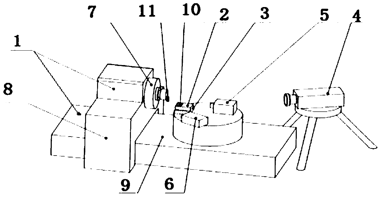
[0045] A precision cutting micro-nano mechanical testing experimental platform, the main device diagram is as follows figure 1 As shown, it includes a three-axis ultra-precision machine tool 1, a three-way micro-motion table 2, a three-way dynamometer 3, a laser displacement sensor 4, a high-speed camera 5, and a thermal imager 6; the three-way micro-motion table 2 is installed on the three-way On the dynamometer 3, the three-way dynamometer is fixed on the workbench of the three-axis ultra-precision machine tool 1, and the laser displacement sensor 4, the high-speed camera 5, and the thermal imager 6 are focused on the cutting position. The three-axis ultra-precision machine tool 1 includes a machine tool spindle 7 , a machine tool X axis 8 , and a machine tool Z axis 9 . During the cutting process, the three-way dynamometer 3 collects the change process data of the cutting force, the laser displacement sensor 4 collects vibration data, the high-speed camera 5 collects chip f...

Embodiment 2

[0053] The method for implementing the above-mentioned precision cutting micro-nano mechanical testing experimental platform specifically includes the following steps:

[0054] S1. Ensure that the working characteristics of each shaft system of the three-axis ultra-precision machine tool are normal, so that the ultra-precision lathe is warmed up until the lathe reaches thermal stability; install the tool of the ultra-precision lathe, and complete the dynamic balance adjustment of the tool;

[0055] S2 Install the sample on the three-way micro-motion table, and the three-way micro-motion table is installed on the three-way dynamometer; the tool setting process is realized by adjusting the three-way micro-motion table;

[0056] S3. Turn on the three-way dynamometer, laser displacement sensor, high-speed camera, and thermal imager; focus the laser displacement sensor, high-speed camera, and thermal imager on the cutting position of the three-axis ultra-precision machine tool to mo...


PUM


Abstract

The invention discloses a micro-nano mechanical testing experimental platform and method for precision cutting. The experimental platform comprises a three-axis ultraprecise machine tool, a three-direction micro table, a three-direction dynamometer, a laser displacement sensor, a high speed camera and a thermal imager. The three-direction micro table is mounted on a three-direction dynamometer, the three-direction dynamometer is fixed to a worktable of the three-axis ultraprecise machine tool, and the laser displacement sensor, the high speed camera and the thermal imager focus on a cutting position. A cutting surface forming process, cutting deformation breakage, a cutting force, a cutting temperature, a cutting depth, cutting vibration and the like in a cutting experimental process can be observed and measured. The micro-nano mechanical testing experimental platform and method for precision cutting can provide platform and method support for researching a material removal mechanism,a high quality cutting surface forming mechanism, a cutting deformation breaking rule and the like.

Description

technical field [0001] The invention relates to the field of material micro-mechanical testing, in particular to an experimental platform and method for precision cutting micro-nano mechanical testing. Background technique [0002] Due to the strong adaptability of cutting processing, high production efficiency, it is not limited by the material, size and quality of parts, and can obtain better processing surface and processing accuracy. It is a common method in ultra-precision processing of materials. However, for tungsten alloys, titanium alloys and other high-hardness, high-density hard and brittle metal materials that are difficult to machine, due to problems such as large cutting force, high temperature in the cutting area, and severe tool wear during processing, it is easy to cause pits on the processed surface of the material. and processing defects such as microcracks. [0003] In order to obtain a high-quality machined surface, it is necessary to study the mechanic...

Claims


Application Information

Patent Timeline
Patent Type & Authority Applications(China)
IPC IPC(8): B23Q17/09
CPCB23Q17/0952B23Q17/0966B23Q17/0971B23Q17/0985
Inventor 杜文浩潘延安李佳伟
Owner INST OF MACHINERY MFG TECH CHINA ACAD OF ENG PHYSICS
Why Eureka
Try Eureka