
Electric automatic ceramic tile edging equipment

A technology of electrical automation and edging equipment, which is applied in the direction of grinding/polishing equipment, metal processing equipment, and machine tools suitable for grinding the edge of workpieces, etc. Decoration aesthetics and other issues, to achieve the effect of reducing temperature, ensuring neatness, and reducing labor intensity

Inactive Publication Date: 2020-06-05
罗霞
View PDF0 Cites 0 Cited by
  • Summary
  • Abstract
  • Description
  • Claims
  • Application Information

AI Technical Summary

Problems solved by technology

[0006] The purpose of the present invention is to provide an electric automatic tile edging equipment to solve the problem that the currently used tile edging equipment proposed in the above background technology generally requires manual hand-held grinding equipment to polish the tiles, but the hand-held equipment cannot be kept stable and cannot be guaranteed. The neatness of the edging will affect the aesthetics of the later decoration and the tile edging equipment currently used generally uses a polishing disc for one-time polishing, but sometimes too much polishing will cause the tiles to break, and it will be a waste of time if you perform multiple polishing , which reduces the work efficiency

Method used


Image

  • Electric automatic ceramic tile edging equipment
  • Electric automatic ceramic tile edging equipment
  • Electric automatic ceramic tile edging equipment

Examples


Embodiment Construction

[0022] The technical solutions in the embodiments of the present invention will be clearly and completely described below in conjunction with the accompanying drawings in the embodiments of the present invention. Obviously, the described embodiments are only a part of the embodiments of the present invention, rather than all the embodiments. Based on the embodiments of the present invention, all other embodiments obtained by those of ordinary skill in the art without creative work shall fall within the protection scope of the present invention.

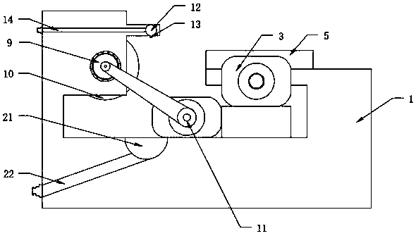
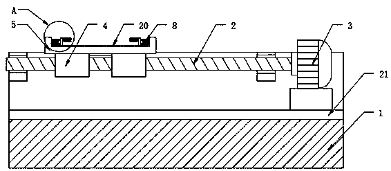
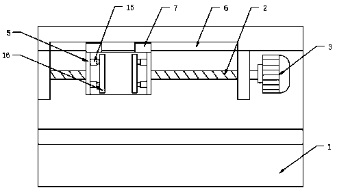
[0023] See Figure 1-5 , The present invention provides a technical solution: an electric automatic ceramic tile edging equipment, including a body 1, the top side of the body 1 is movably provided with a screw rod 2 through a bearing, and the inner side of the body 1 is fixedly provided by a fixed block There is a first motor 3, the first motor 3 is connected with the screw rod 2, the screw rod 2 is sleeved with a movable block 4, the t...


PUM


Abstract

The invention discloses electric automatic ceramic tile edging equipment. The equipment comprises a machine body, one side of the top end of the machine body is movably provided with a lead screw through a bearing, one side inside the machine body is fixedly provided with a first motor through a fixed block, the first motor is connected with the lead screw, a movable block is arranged on the leadscrew in a sleeving mode, the top end of the movable block is fixedly provided with a placing plate, a groove is formed in one side, of the placing plate, of the machine body, a sliding block is fixedly arranged on one side of the placing plate, the sliding block is movably arranged inside the groove, fixing mechanisms are fixedly arranged on two sides of the top end of the placing plate, a fixedrod is movably arranged on the other side of the top end of the machine body through a bearing, a plurality of grinding discs are mounted on the fixed rod, and a second motor is fixedly arranged on one side of the bottom end inside the machine body. According to the equipment, the structure is simple in and is convenient to use, the grinding discs are driven to rotate by the fixed rod to grind anedge of a ceramic tile conveniently, and the situation that the ceramic tile is broken when grinding is avoided.

Description

Technical field [0001] The invention relates to the technical field of electrical equipment, in particular to an electrical automatic tile edging equipment. Background technique [0002] Ceramic tiles, also known as ceramic tiles, are refractory metal oxides and semi-metal oxides, which are formed by grinding, mixing, pressing, glazing, and sintering to form a kind of acid and alkali resistant porcelain or stone. Or decorative materials, called ceramic tiles, whose raw materials are mostly a mixture of clay, quartz sand, etc., and the edges of the tiles need to be polished when installing the tiles at the site. [0003] However, the currently used ceramic tile edging equipment has the following shortcomings: [0004] 1. The currently used ceramic tile edging equipment generally requires manual hand-held polishing equipment to polish the ceramic tiles, but the handheld equipment cannot maintain stability and cannot guarantee the neatness of the edging, which affects the aesthetics of...

Claims


Application Information

Patent Timeline
Patent Type & Authority Applications(China)
IPC IPC(8): B24B9/06B24B27/00B24B55/06B24B55/02B24B41/06B24B41/02B24B47/04
CPCB24B9/06B24B27/0076B24B41/02B24B41/06B24B47/04B24B55/02B24B55/06
Inventor 罗霞
Owner 罗霞
Learn More