Transfer device for airplane lubricating oil system

A technology of lubricating oil system and transfer device, which is applied in the aviation field, can solve problems such as reducing service life and increasing engine wear, and achieves the effects of preventing fluctuations, ensuring oil supply efficiency, and strengthening the support box.

Pending Publication Date: 2020-06-05
石家庄飞机工业有限责任公司
View PDF1 Cites 1 Cited by
  • Summary
  • Abstract
  • Description
  • Claims
  • Application Information

AI Technical Summary

Problems solved by technology

[0004] Although the above technical solution solves the lubricating oil supply problem, after the aero-engine is assembled, it is necessary to test the loss of the lubricating oil system to meet the design requirements. Since the lubricating oil returned from the engine will contain air and gas, it will be milky, and if it is recirculated into The engine will not be fully lubricated, which will increase the wear and tear of the engine and reduce the service life

Method used


Image

  • Transfer device for airplane lubricating oil system
  • Transfer device for airplane lubricating oil system

Examples


Embodiment 1

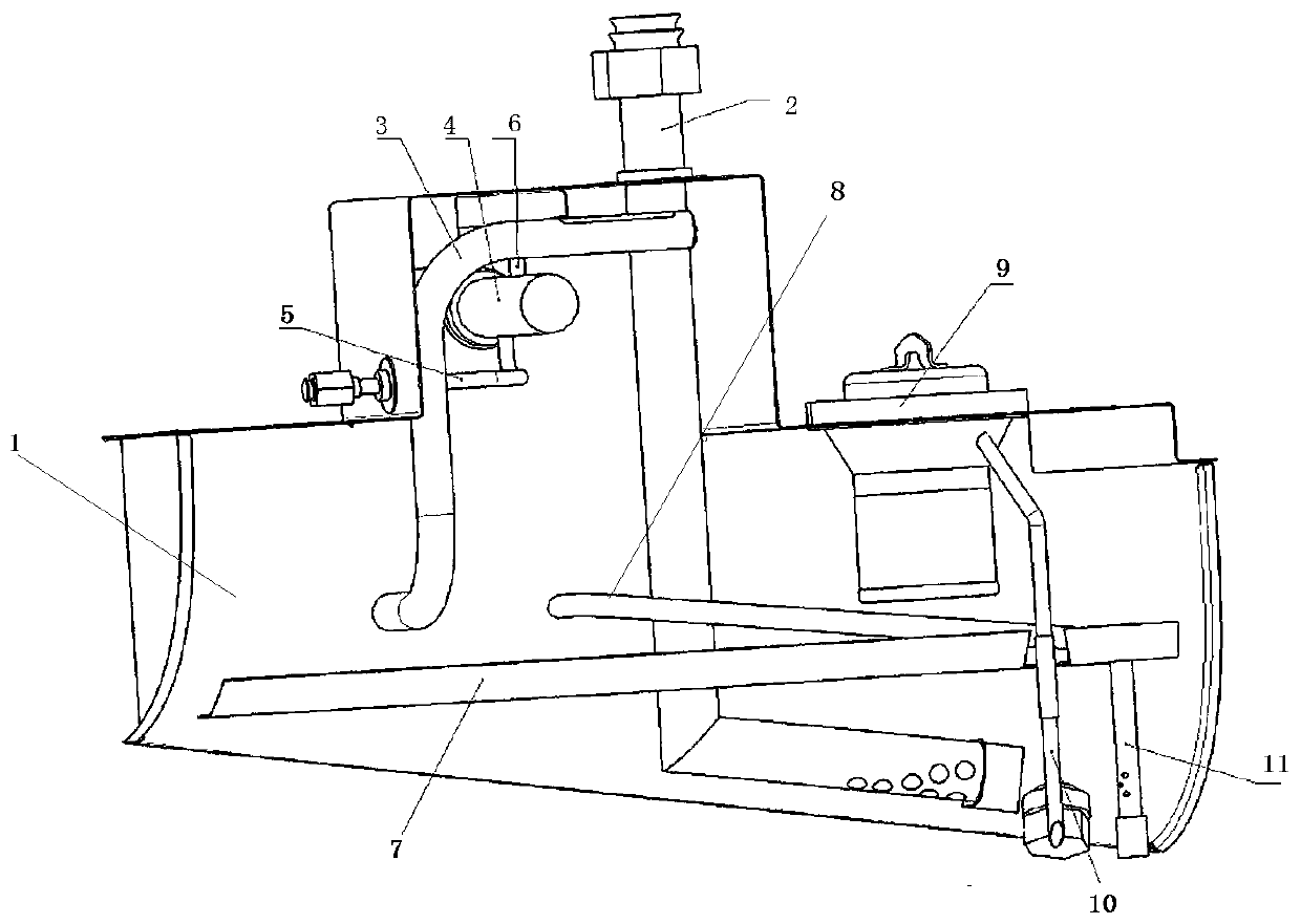
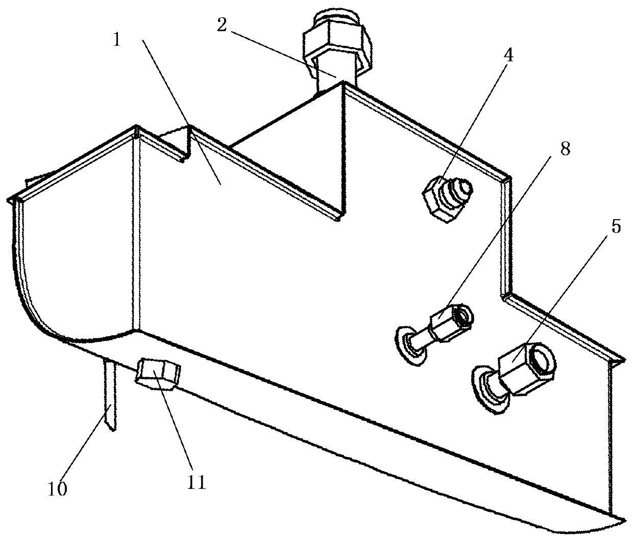
[0039] Such as Figure 1-2 As shown, a transfer device for an aircraft lubricating oil system, a transfer device for an aircraft lubricating oil system, includes a box body 1, an oil supply pipe 2 arranged on the box body 1, an oil return pipe 3 arranged on the box body 1, a set The oil-gas separation device in the case 1 and the exhaust pipe 5 arranged on the case 1; the oil supply pipe 2 runs through the case 1 and communicates with the case 1; the oil return pipe 3 runs through the case The box 1 is connected to the upper part of the box 1; the exhaust pipe 5 runs through the box 1 and communicates with the outside of the box 1; the oil-gas separation device is arranged on the top of the box 1; the oil-gas separation The air outlet of the device communicates with the exhaust pipe 5; the oil supply pipe 2 is L-shaped; the tail end of the oil supply pipe 2 is arranged along the bottom of the box body 1; the tail end of the oil supply pipe 2 is not equipped with Oil supply ho...

Embodiment 2

[0041] Such as Figure 1-2 As shown, a transfer device for an aircraft lubricating oil system, a transfer device for an aircraft lubricating oil system, includes a box body 1, an oil supply pipe 2 arranged on the box body 1, an oil return pipe 3 arranged on the box body 1, a set The oil-gas separation device in the case 1 and the exhaust pipe 5 arranged on the case 1; the oil supply pipe 2 runs through the case 1 and communicates with the case 1; the oil return pipe 3 runs through the case The box 1 is connected to the upper part of the box 1; the exhaust pipe 5 runs through the box 1 and communicates with the outside of the box 1; the oil-gas separation device is arranged on the top of the box 1; the oil-gas separation The air outlet of the device communicates with the exhaust pipe 5; the oil supply pipe 2 is arranged along the bottom of the box; the downward side of the oil supply pipe 2 is provided with an oil supply hole; the oil outlet of the oil-gas separation device On...


PUM


Abstract

The invention discloses a transfer device for an airplane lubricating oil system. The transfer device comprises a box body, an oil supply pipe arranged on the box body, an oil return pipe arranged onthe box body, an oil-gas separation device arranged in the box body and an exhaust pipe arranged on the box body, wherein the oil supply pipe penetrates through the box body and communicates with thebox body, the oil return pipe penetrates through the box body and communicates with the upper part of the box body, the exhaust pipe penetrates through the box body and communicates with the outside of the box body, the oil-gas separation device is arranged at the upper part of the box body, and a gas outlet of the oil-gas separation device communicates with the exhaust pipe. According to the device, a centrifugal oil-gas separator is arranged in the box body, fuel gas and air in lubricating oil can be separated, meanwhile, the separated air and fuel gas are discharged out of the box body, secondary mixing of the air, the fuel gas and the lubricating oil is avoided, a compartment with a heating function is arranged in the box body, the lubricating oil is rapidly heated when an engine is started, severe fluctuation of the lubricating oil due to changes of the attitude of an airplane and the like is prevented, and the box body can be supported in a reinforced mode.

Description

technical field [0001] The invention belongs to the technical field of aviation, and in particular relates to a transfer device for an aircraft lubricating oil system. Background technique [0002] In the lubricating oil system used in aviation turboprop engines, the engine delivers the lubricating oil and sucks back the lubricating oil from the engine to continuously circulate along a closed loop. Friction, less wear, and at the same time take away the heat generated by friction and the inclusions between relative moving surfaces; [0003] The application number is CN201520830237.2, the application date is 2015.10.23, and the utility model patent named "an integrally embedded lubricating oil tank", the specific content is as follows: The utility model discloses an integrally embedded lubricating oil tank, The lubricating oil tank includes an outer wall and an inner wall. The lubricating oil tank is a drum-shaped structure with a through hole in the middle. The shape of th...

Claims


Application Information

Patent Timeline
Patent Type & Authority Applications(China)
IPC IPC(8): F15B1/26F16N39/04F16N39/06
CPCF15B1/26F16N39/04F16N39/06
Inventor 李志强张红苗徐皓阁
Owner 石家庄飞机工业有限责任公司
Why Eureka
Try Eureka