
Method for identifying operation mode under underdetermined condition based on blind source separation technology

A blind source separation and modal recognition technology, applied in character and pattern recognition, pattern recognition in signals, complex mathematical operations, etc., can solve problems such as harm and deformation, and achieve wide application prospects and benefits.

Active Publication Date: 2020-06-05
BEIJING INSTITUTE OF TECHNOLOGYGY
View PDF5 Cites 7 Cited by
  • Summary
  • Abstract
  • Description
  • Claims
  • Application Information

AI Technical Summary

Problems solved by technology

[0006] The purpose of the present invention is to solve the problems of deformation and harm caused by the mechanical system working for many years, and to provide a method for operating mode recognition under underdetermined conditions based on blind source separation technology

Method used


Image

  • Method for identifying operation mode under underdetermined condition based on blind source separation technology
  • Method for identifying operation mode under underdetermined condition based on blind source separation technology
  • Method for identifying operation mode under underdetermined condition based on blind source separation technology

Examples


Embodiment 1

[0081] The five-degree-of-freedom spring-damper-mass system of the present embodiment, such as figure 2 shown. The five-degree-of-freedom spring-damper-mass system of this embodiment includes five mass blocks, five dampers, and five springs each. These spring-dampers are all constant and do not change with time.

[0082]

[0083] Convert the dynamic equation (16) into a state space equation, and use SIMULINK to construct a state space simulation model according to the state space equation, such as figure 2 . In the above formula, M, C, K are the mass, stiffness and damping matrix respectively, which is the system response, as shown in formula (17). F(t) applies a transient impact of 120N for 0.01s in this example.

[0084]

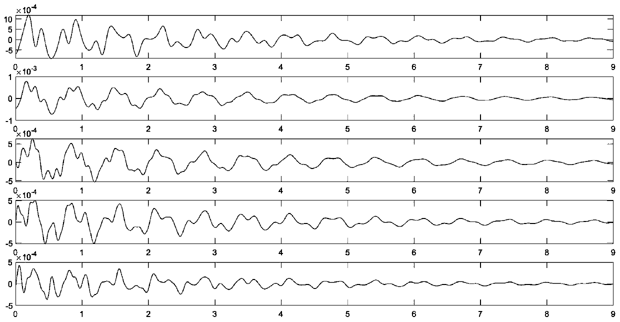
[0085] Gauss white noise excitation is applied to the five mass blocks respectively, and the responses of the five mass blocks in the system are obtained. The five-degree-of-freedom displacement is used as the response signal sample for identif...

Embodiment 2

[0108] This implementation uses the same five-DOF spring-damper-mass simulation system as Example 1, such as figure 2 shown. The system composition and parameter settings are the same as those in Example 1.

[0109] Since this example is aimed at the underdetermined situation, three groups of samples are selected in this example, and each group of samples contains the acceleration of three degrees of freedom as the response signal samples used for identification, respectively X 1-3-5 ,X 2-4-5 ,X 1-2-4 , the subscript indicates the serial number of the mass block. The solution result is re-sampled at f=100Hz, the recording time is 10s (t∈[0,10]), and the signal length N=1000.

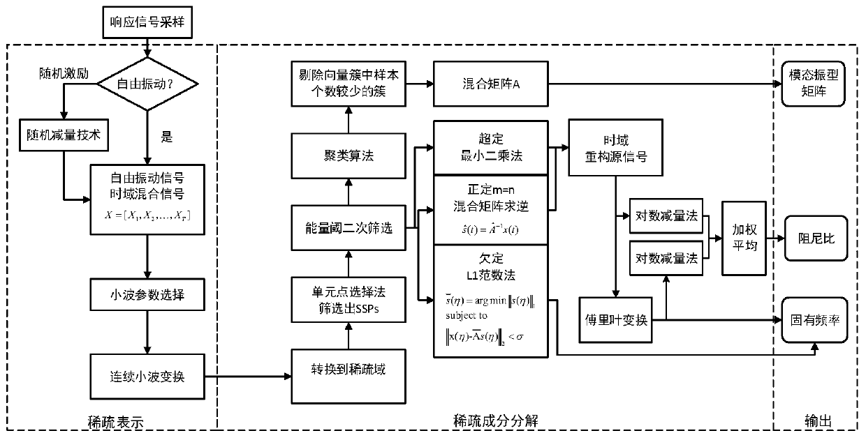
[0110] A blind source separation technology-based operating mode recognition method under underdetermined conditions disclosed in this embodiment includes the following steps:

[0111] Step 1: Make a sparse representation of the free vibration acceleration observation data of the parameter structur...


PUM


Abstract

The invention relates to a method for identifying an operation mode under an underdetermined condition based on a blind source separation technology, and belongs to the field of detection of large land-based platforms, aerospace, ships and buildings. According to the invention, the modal parameter identification precision of the operation modal analysis method based on blind source separation under the conditions of underdetermined conditions, near-frequency modals and the like is improved, the calculation efficiency is improved, and the calculation cost is reduced. Moreover, the dependence ofthe method on prior knowledge such as modal orders in the modal parameter identification process is reduced, and the sensitivity to noise signals is reduced, so that the method is small in calculatedamount, high in robustness and convenient to use. The method can be operated even under the condition of lack of professional knowledge background, and can be widely applied to modal parameter identification under the linear structure underdetermined condition in structural dynamics engineering application.

Description

technical field [0001] The invention relates to an operating mode identification method under underdetermined conditions based on blind source separation technology, in particular to an operating mode parameter identification method based on coefficient component analysis and density clustering, belonging to large land-based platforms, aerospace , Ship and building inspection field. Background technique [0002] With the gradual increase in size, efficiency and complexity of mechanical equipment, various fields such as large land-based platforms, aerospace, ships, and construction have put forward higher requirements for the comprehensive performance of mechanical systems. During the operation of the actual mechanical system, the harmful vibration generated not only affects the safety, stability and reliability of itself and other equipment, but also endangers the health and safety of the operator. At present, on the one hand, designers often adjust the structural parameter...

Claims


Application Information

Patent Timeline
IPC IPC(8): G06K9/00G06K9/62G06F17/14
CPCG06F17/148G06F2218/22G06F2218/04G06F18/2321
Inventor 张发平武锴李果李伊张云贺
Owner BEIJING INSTITUTE OF TECHNOLOGYGY
Learn More