
Correction angle logarithm zigzag waveguide slow wave device

A technology for correcting angles and tortuous waveguides, which is applied to waveguide devices, electrical components, circuit components of time-of-flight electron tubes, etc. It can solve the problems of poor transmission characteristics, increased processing and assembly difficulties, and increased processing and assembly of slow wave structures. Difficulty and other issues to achieve the effect of increasing gain and suppressing oscillation

Active Publication Date: 2020-06-05
UNIV OF ELECTRONICS SCI & TECH OF CHINA
View PDF5 Cites 0 Cited by
  • Summary
  • Abstract
  • Description
  • Claims
  • Application Information

AI Technical Summary

Problems solved by technology

However, the introduction of the attenuator also introduces some problems to the traveling wave tube
First, the introduction of the attenuator makes the slow-wave structure more complex in structure, increasing the difficulty of processing and assembling the slow-wave structure, especially in high-frequency traveling wave tubes, the difficulty of processing and assembling increases sharply; second, the attenuation The introduction of the attenuator will lead to poor impedance matching conditions in the area near the attenuator, making the transmission characteristics worse
In addition, due to the structural complexity brought by the attenuator, usually a traveling wave tube can only be divided into two sections, and the gain of the existing double-section traveling wave tube is generally only about 40dB.
[0004] Generally speaking, although the existing method of using an attenuator to suppress oscillation can increase the gain of the traveling wave tube, the limitation is also very obvious, which greatly restricts the gain of the existing traveling wave tube. Only by increasing the gain of the traveling wave tube Single-stage gain can further improve the overall gain of the traveling wave tube

Method used

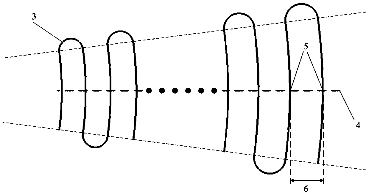

Image

  • Correction angle logarithm zigzag waveguide slow wave device
  • Correction angle logarithm zigzag waveguide slow wave device
  • Correction angle logarithm zigzag waveguide slow wave device

Examples


Embodiment

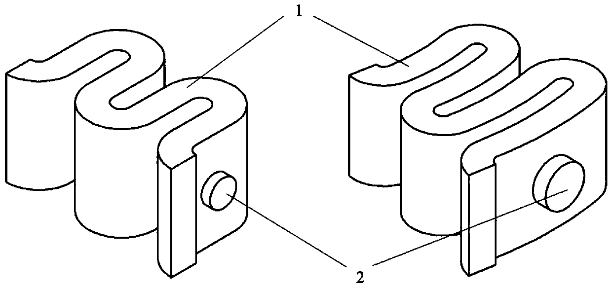
[0022] figure 1 It is a structural comparison diagram of the traditional meandering waveguide slow-wave structure and the modified angle logarithmic meandering waveguide slow-wave structure of the present invention.

[0023] In this example, if figure 1 As shown, a modified angle logarithmic meandering waveguide slow wave device of the present invention includes: a meandering waveguide folded along the corrected angle logarithmic meandering line and a cylindrical electron injection channel;

[0024] In this example, if figure 1 As shown, the left figure is a traditional meander waveguide slow-wave structure, which is a periodic structure, and the right figure is the angle-corrected logarithmic meander waveguide slow-wave structure of the present invention. It can be seen that it is not periodic and is a non-periodic Periodic structure, 1 is meandering waveguide, 2 is electron beam channel;

[0025] The meander waveguide is formed by folding an ordinary rectangular waveguide...


PUM


Abstract

The invention discloses a correction angle logarithm zigzag waveguide slow wave device. The correction angle logarithm zigzag waveguide slow wave device comprises a zigzag waveguide folded along a correction angle logarithm zigzag line and a cylindrical electron beam channel. According to the slow wave device, because of the special zigzag path of the correction angle logarithm zigzag line, the forward electromagnetic waves in a working frequency band can achieve the synchronization conditions through electron beams, other electromagnetic waves cannot achieve the synchronization conditions with the electron beams, and therefore the purpose of restraining oscillation while guaranteeing the normal work of the traveling wave tube is achieved. Besides, the slow wave device abandons a centralized attenuator in a traditional traveling wave tube, so that the reflection caused by impedance mismatching at the position of the original attenuator can be avoided, and the slow wave device has the advantage of improving the transmission characteristic of the slow wave structure of the traveling wave tube.

Description

technical field [0001] The invention belongs to the technical field of microwave power amplifiers, and more specifically relates to a logarithmic meander waveguide slow-wave device for correcting angles. Background technique [0002] Traveling wave tube is a kind of microwave power amplifier, which has the characteristics of high gain, large bandwidth, high efficiency, high power and high reliability. It has a very wide range of applications in many fields such as radar, satellite, and electronic countermeasures. [0003] Existing traveling wave tubes are usually designed in two sections, that is, an attenuator is used to cut off the slow wave structure from the middle. This is because the existing traveling wave tube will excite some oscillation signals more or less during the working process. If the oscillation signal is too strong, it will affect the normal operation of the traveling wave tube. The higher the gain of the single-segment traveling wave tube, the more vibrat...

Claims


Application Information

Patent Timeline
Patent Type & Authority Applications(China)
IPC IPC(8): H01J23/24H01P9/00
CPCH01J23/24H01P9/00
Inventor 许多邵伟何腾龙王禾欣王战亮宫玉彬
Owner UNIV OF ELECTRONICS SCI & TECH OF CHINA
Learn More