
Precise manipulator carrying system

A handling system and manipulator technology, applied in the field of bearing processing, can solve the problems of low work efficiency, high production cost, high labor intensity, etc., and achieve the effect of saving use cost, reducing labor intensity, precise and stable control

Active Publication Date: 2020-06-09
WENZHOU POLYTECHNIC
View PDF7 Cites 2 Cited by
  • Summary
  • Abstract
  • Description
  • Claims
  • Application Information

AI Technical Summary

Problems solved by technology

However, the loading and unloading operations of the existing processing systems used for bearing production mostly rely on manual control, which is not only labor-intensive and low-efficiency, but also the operation of adding grease during production requires additional designated stations, and the production cost High, long processing cycle, low work efficiency

Method used


Image

  • Precise manipulator carrying system
  • Precise manipulator carrying system
  • Precise manipulator carrying system

Examples


Embodiment 1

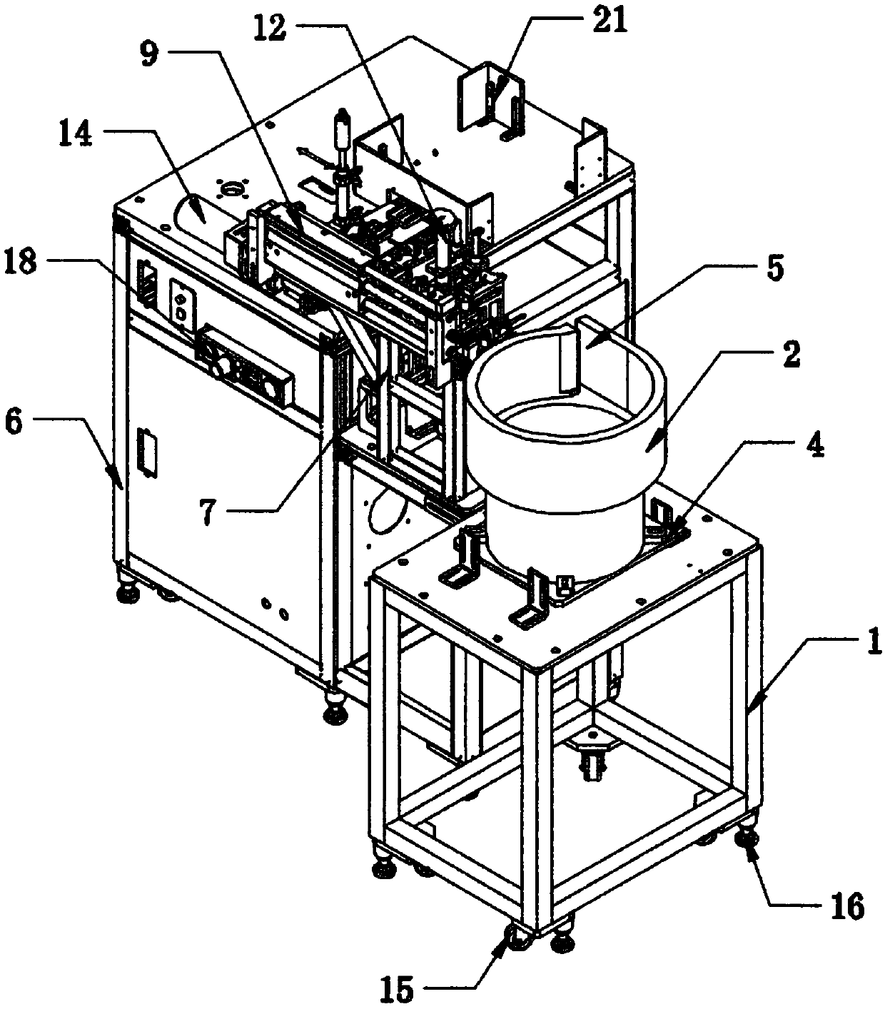
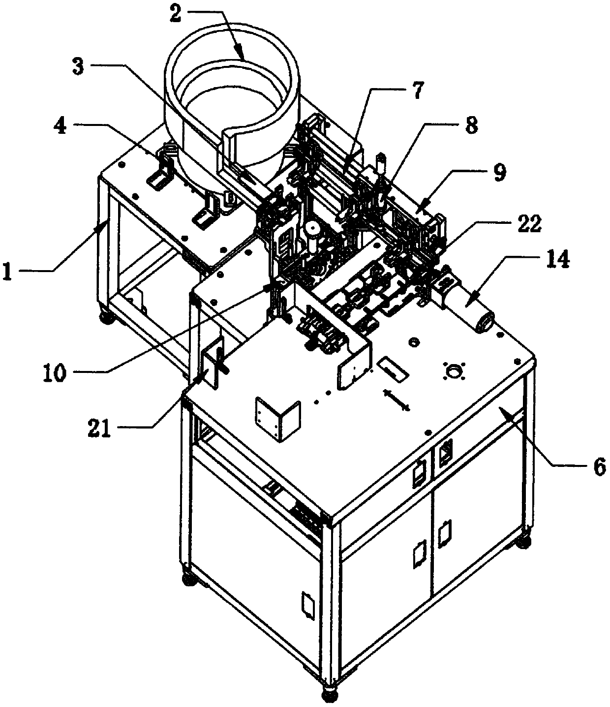
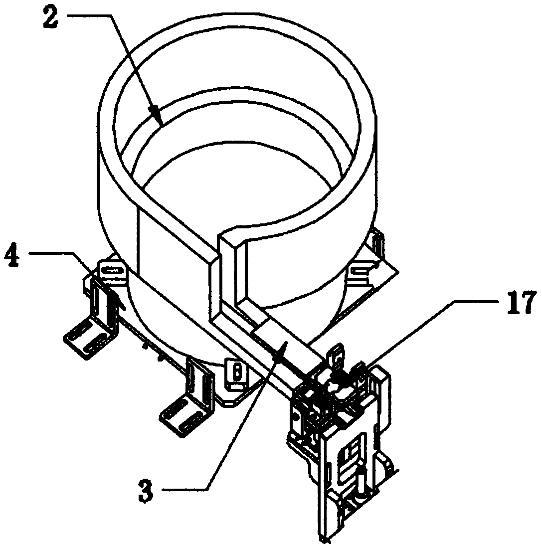
[0029] Such as Figure 1 to Figure 6 As shown, the automatic processing device for bearings according to a preferred embodiment of the present invention includes a bearing output mechanism, a gantry-type manipulator mechanism, a grease adding mechanism and a conveyor belt 22 . Wherein, the bearing output mechanism includes a feeding rack 1, a vibrating plate 2 and a feeding track 3, the middle part of the top surface of the feeding rack 1 is longitudinally fixed with a U-shaped limiting plate 4, and the vibrating plate 2 is vertically fixed on the limiting plate 4 In the middle part of the inner wall of the vibrating plate 2, an L-shaped material guide port 5 is provided on the side of the end away from the limit plate 4, and the feeding track 3 is fixed laterally on the side of the vibrating plate 2 on the side of the material guide port 5 through a tripod, and on the side of the feeding rack 1. An operation table 6 is fixedly arranged, and the gantry-type manipulator mechani...

Embodiment 2

[0031] see Figure 1-6 , in the present invention, the feeding rack 1 is a hollow metal frame and the bottom surface is provided with a guide wheel 15 vertically movable through the corner code, and the bottom surface of the corner code on one side of the guide wheel 15 is fixedly provided with an adjustable foot 16; The frequency converter is controlled and driven by a built-in motor, and the feeding track 3 on the side of the vibrating plate 2 is a concave metal power slide rail;

[0032]In a preferred embodiment, a control panel 18 is fixed laterally on the front side surface of one end of the console 6 away from the loading rack 1, and the control panel 18 communicates with the bearing output mechanism, the gantry-type manipulator mechanism, the grease adding mechanism and the conveying mechanism respectively through the controller. The driving motor 14 signal connection of the belt 22; the driving motor 14 is a frequency conversion type stepping motor, and the output shaf...

Embodiment 3

[0036] see Figure 1-6 , the working principle of the automatic processing device of the bearing of a preferred embodiment of the present invention is: when in use, the bearing with processing is placed in the vibrating plate 2 and utilizes the control panel to regulate the rotation parameters of the vibrating plate 2, and the vibrating plate 2 and the feeding Under the joint action of the rails 3, the bearings are guided into the surface of the feeding rail 3 one by one by the material guide port 5 and the automatic feeding operation is completed by using the travel switch 17, and the pneumatic material moving plate 9 supporting the surface of the stand 7 above the operating table 6 is driven by compressed gas Move the material shifting manipulator 8 left and right to realize the fast and stable feeding of cyclic clamping and grease injection operations. Adjust the deflection angle of the turntable 11 through the adjustment lever to make it horizontal to facilitate the next op...


PUM


Abstract

The invention discloses a precise manipulator carrying system which comprises a bearing output mechanism, a gantry type manipulator mechanism, a lubricating grease adding mechanism and a conveyor belt. The bearing output mechanism comprises a feeding frame, a vibration disc and a feeding rail, a U-shaped limiting plate is longitudinally and fixedly arranged in the middle of the top surface of thefeeding frame, the vibration disc is vertically and fixedly arranged in the middle of the inner wall of the limiting plate, an L-shaped material guide opening is formed in the side face of the end, away from the limiting plate, of the vibration disc, and the feeding rail is transversely and fixedly arranged on the side face, on one side of the material guide opening, of the vibration disc througha tripod; the gantry type manipulator mechanism comprises a supporting vertical frame and a material moving mechanical arm, and the material moving mechanical arm is vertically and fixedly arranged atthe position, at one end of the side face of a pneumatic material moving plate, above the feeding rail through a connecting piece; and the lubricating grease adding mechanism comprises a rotary tableand a lubricating grease injector, the rotary table is obliquely and movably arranged on one side of the material moving mechanical arm through an adjusting rod arranged at one end of the side face of a connecting frame, and a lubricating grease injector is vertically and fixedly arranged above the rotary table through a circular through hole formed in the middle of one end of the top surface ofthe connecting frame.

Description

technical field [0001] The invention belongs to the technical field of bearing processing, and in particular relates to a precision manipulator handling system. Background technique [0002] Bearing is an important part of mechanical equipment. Its main function is to support the mechanical rotating body, reduce the friction coefficient during its movement, and ensure its rotation accuracy. Under a certain load, the number of revolutions or hours experienced by the bearing before pitting occurs is called the bearing life. The life of rolling bearings is defined by the number of revolutions (or the number of hours of work at a certain speed): bearings within this life should have initial fatigue damage (flaking or defect) on any of their bearing rings or rolling elements. However, no matter in the laboratory test or in actual use, it can be clearly seen that the actual life of bearings with the same appearance under the same working conditions is quite different. In additio...

Claims


Application Information

Patent Timeline
Patent Type & Authority Applications(China)
IPC IPC(8): B65G37/00B65G27/00B65G47/90B05C13/02B05C5/02
CPCB05C5/0208B05C13/02B65G27/00B65G37/00B65G47/90B65G2201/0214
Inventor 倪步喜
Owner WENZHOU POLYTECHNIC
Learn More