Supporting truss rod and space truss structure

A technology for supporting trusses and space trusses, applied in the field of space optical remote sensing, can solve the problems of large stress at the bonding position and poor reliability of the bonding process, and achieve the effect of large connection surface, simple and reliable screw connection, and easy assembly

Pending Publication Date: 2020-06-09
XI'AN INST OF OPTICS & FINE MECHANICS - CHINESE ACAD OF SCI
View PDF0 Cites 4 Cited by
  • Summary
  • Abstract
  • Description
  • Claims
  • Application Information

AI Technical Summary

Problems solved by technology

[0007] In order to solve the problems of high stress at the bonding position and poor reliability of the bonding process existing in the existing space truss structure, the present invention provides a supporting truss rod and a space truss structure. Reliability and convenience of structural processing and assembly

Method used


Image

  • Supporting truss rod and space truss structure
  • Supporting truss rod and space truss structure
  • Supporting truss rod and space truss structure

Examples


Embodiment Construction

[0036] The core idea of ​​the present invention is to adopt a low-stress pre-embedding method to reduce the assembly stress and thermal stress that may be generated when the truss rod is bonded to the metal parts, and to improve the connection strength and reliability. At the same time, the integrated support truss rod assembly can simplify the assembly process of the truss structure.

[0037] Below in conjunction with accompanying drawing and specific embodiment carry out further detailed description:

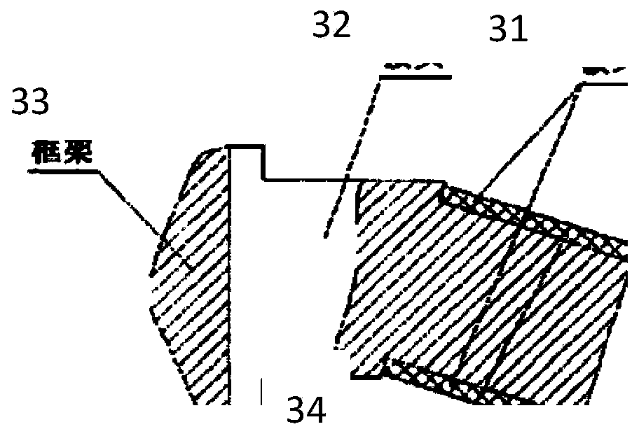
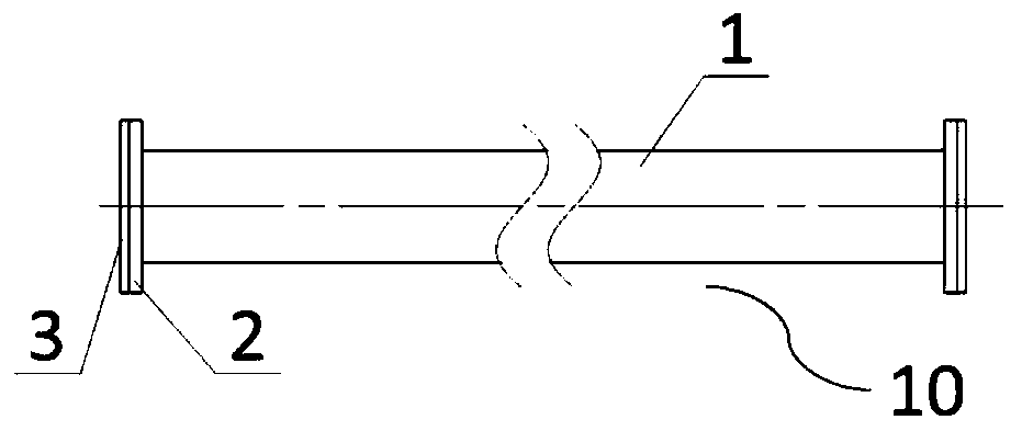
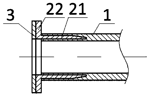
[0038] figure 2 and image 3 They are the front view and end cross-sectional view of the supporting truss bar respectively. The assembly includes the truss bar body 1 and the connection assembly arranged at both ends of the truss bar body 1 , wherein the connection assembly includes the embedded part 2 and the metal bottom plate 3 . The truss rod body 1 is a hollow rod wound with M40 carbon fiber material. The embedded part 2 is made of carbon fiber reinforced SiC ceramic ...


PUM


Abstract

The invention relates to a supporting truss rod and a space truss structure. The problems that according to an existing space truss structure, the glue joint position is large in stress, and the bonding technology is poor in reliability are solved. The supporting truss rod comprises a truss rod body and connecting assemblies arranged at the two ends of the truss rod body. The truss rod body is a hollow rod formed through winding of carbon fiber materials. Each connecting assembly comprises an embedded piece and a metal bottom plate, wherein the material of the embedded piece is a carbon fiberenhanced SiC ceramic composite material and comprises a tubular embedded end and a connecting flange located at one end portion of the embedded end, the embedded end is embedded in the rod wall of thetruss rod body, the outer wall diameter of the embedded end is smaller than the outer diameter of the truss rod body, the inner wall diameter of the embedded end is larger than the inner diameter ofthe truss rod body, and the metal bottom plate is an annular metal plate adaptive to the connecting flange and is bonded and fixed to the connecting flange. The low-stress embedding manner is adopted,assembling stress and heat stress possibly generated during truss rod and metal piece bonding are relieved, and the truss structure assembling technology is simplified.

Description

technical field [0001] The invention belongs to the technical field of space optical remote sensing, and in particular relates to a supporting truss rod and a space truss structure. Background technique [0002] With the gradual development of space optical remote sensors in the direction of large aperture and long focal length, the space truss structure has been widely used in the main support structure of optical remote sensors. The supporting truss rod is the core component of the space truss, and its structural design determines the reliability and convenience of the processing and assembly of the entire truss component. [0003] The connection mode of the existing space truss structure is as follows: figure 1 As shown, the truss rod 31 is made of carbon fiber composite material, and the end is sleeved (bonded, bonded through the glue layer 34 ) to the truss joint 32 , and the truss joint 32 is then fixed to the support frame 33 by screws. The above solution has the fo...

Claims


Application Information

Patent Timeline
IPC IPC(8): F16M11/04G01N21/01G01N21/17
CPCF16M11/04G01N21/01G01N21/17G01N2021/0112G01N2021/1793
Inventor 孙丽军李思远李立波武俊强张兆会王飞橙贾昕胤王锋
Owner XI'AN INST OF OPTICS & FINE MECHANICS - CHINESE ACAD OF SCI
Why Eureka
Try Eureka