A carbon nanotube film frequency selective surface and its preparation method, radome

A technology of carbon nanotube thin film and frequency selective surface, which is applied in the direction of electrical components, antennas, etc., can solve the problems of weight gain, corrosion-prone structure, thermal mismatch, etc., and achieve high production efficiency, weight corrosion resistance, and thermal mismatch rate low effect

Active Publication Date: 2018-02-27
NAT UNIV OF DEFENSE TECH
View PDF3 Cites 0 Cited by
  • Summary
  • Abstract
  • Description
  • Claims
  • Application Information

AI Technical Summary

Problems solved by technology

[0004] The purpose of the present invention is to provide a carbon nanotube film frequency selective surface and its preparation method, radome, the present invention mainly solves the thermal mismatch and easy corrosion caused by the application of metal FSS to FRP and its structure in the prior art and structural weight gain technical issues

Method used


Image

  • A carbon nanotube film frequency selective surface and its preparation method, radome
  • A carbon nanotube film frequency selective surface and its preparation method, radome
  • A carbon nanotube film frequency selective surface and its preparation method, radome

Examples


preparation example Construction

[0035] see Figure 9 On the other hand, the present invention also provides a preparation method comprising the steps of:

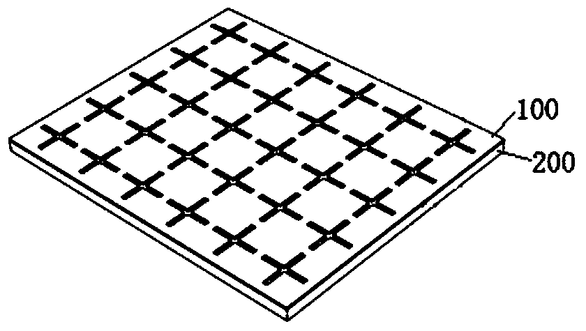
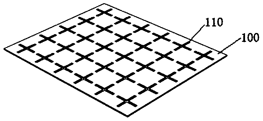
[0036] 1) Forming: forming the carbon nanotube film layer 100 according to a preset pattern;

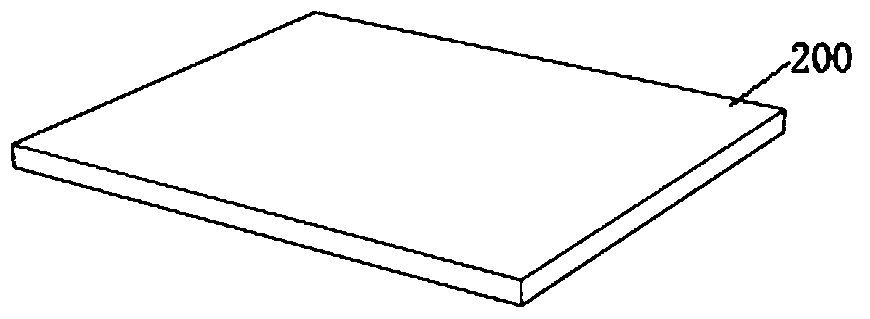
[0037] 2) Paste: Paste the carbon nanotube film layer 100 with a preset pattern on the fiber-reinforced resin layer;

[0038] 3) Press molding: the fiber-reinforced resin pasted with the carbon nanotube film layer 100 is press-cured.

[0039] FSS with high thermal stability can be obtained by adopting the above steps. Example

Embodiment 1

[0041] Prepare FSS sample 1 according to the following steps:

[0042] 1) The selected conductivity is about 1×10 5 A carbon nanotube film with a S / m thickness of 15 μm, engraving a plurality of cross-shaped through holes regularly arranged on the carbon nanotube film by laser engraving;

[0043] 2) A quartz fiber reinforced epoxy composite laminate with a thickness of about 1.3 mm was prepared from 10 layers of quartz fiber fabric (each layer thickness is about 0.1 mm) by vacuum bagging process, and epoxy resin was used as a binder, which will have A plurality of carbon nanotube film layers with cross-shaped through holes are pasted to the surface of the quartz fiber reinforced epoxy composite foam sandwich panel substrate;

[0044] 3) pressurized and solidified by a vacuum bag pressure method to obtain a band-pass carbon nanotube film FSS.

Embodiment 2

[0046] Prepare FSS sample 2 according to the following steps:

[0047] 1) The selected conductivity is about 2×10 5 Carbon nanotubes with a S / m thickness of 100 μm are thin, and a plurality of Y-shaped through holes arranged regularly and periodically are carved on the carbon nanotube film by mechanical engraving;

[0048] 2) The quartz fiber reinforced cyanate ester resin composite foam sandwich panel was prepared by vacuum infusion process as the substrate, wherein the upper and lower panels of the foam sandwich panel were 1 mm thick quartz fiber reinforced cyanate ester composite material laminated board, and the foam core material It is a PMI foam with a thickness of 10mm; a carbon nanofilm layer with multiple Y-shaped openings is bonded to the surface of the quartz fiber reinforced cyanate composite foam sandwich panel by using cyanate resin;

[0049] 3) pressurized and solidified by a vacuum bag pressure method to obtain a band-pass carbon nanotube film FSS.


PUM

PropertyMeasurementUnit
electrical conductivityaaaaaaaaaa
thicknessaaaaaaaaaa
thicknessaaaaaaaaaa

Abstract

The invention discloses a carbon nanotube film frequency selective surface, a preparation method thereof and a radome. The surface includes a substrate and a carbon nanotube thin film layer arranged on the substrate, the substrate is a fiber-reinforced resin composite material; the carbon nanotube thin film layer is a carbon nanotube thin film with periodic openings. The frequency selective surface technology of the carbon nanotube thin film of the invention is simple to implement, has good matching with the substrate of the fiber-reinforced resin composite material, has small weight gain, and is corrosion-resistant, and can be widely used in devices such as composite material radomes or filters.

Description

technical field [0001] The invention relates to the technical field of frequency selective surfaces, in particular to a carbon nanotube film frequency selective surface, a preparation method thereof, and a radome. Background technique [0002] Frequency Selective Surfaces (FSS for short) is a two-dimensional periodic array structure, which is a spatial filter in essence, and is composed of identical units arranged at regular intervals in the two-dimensional direction. FSS has a specific frequency selection effect and is widely used in microwave, infrared to visible light bands. Frequency selective surfaces include patch types and slot types. The patch type is obtained by periodically covering the surface of the medium with the same metal patches. Generally speaking, it is used as a band-stop filter, which can play the role of low-frequency transmission and high-frequency reflection. The slotting type is obtained by periodically opening slots on the metal plate. From the pe...

Claims


Application Information

Patent Timeline
Patent Type & Authority Patents(China)
IPC IPC(8): H01Q17/00
Inventor 鞠苏张鉴炜江大志石刚蒋彩林少锋朱璞
Owner NAT UNIV OF DEFENSE TECH
Why Eureka
Try Eureka