Pressure relief device for high-pressure constant-volume combustion bomb

A technology of constant volume incendiary bomb and pressure relief device, which is applied in measurement devices, internal combustion engine testing, engine testing and other directions, can solve the problems of bulky bomb body, limited pressure range, and difficulty in heating the incendiary bomb cavity.

Pending Publication Date: 2020-06-09
WUHAN UNIV OF TECH
View PDF0 Cites 2 Cited by
  • Summary
  • Abstract
  • Description
  • Claims
  • Application Information

AI Technical Summary

Problems solved by technology

[0003] At present, a large number of scholars in the field of combustion at home and abroad use incendiary bomb technology to study the process of laminar flame propagation, but only some research groups are conducting research on laminar flame propagation under high-pressure conditions. Cavity incendiary bombs can realize high-pressure research, but the integrated arrangement of incendiary bomb cavity and pressure relief cavity has the probl

Method used


Image

  • Pressure relief device for high-pressure constant-volume combustion bomb
  • Pressure relief device for high-pressure constant-volume combustion bomb
  • Pressure relief device for high-pressure constant-volume combustion bomb

Examples


Embodiment Construction

[0021] This part will describe the specific embodiment of the present invention in detail, and the preferred embodiment of the present invention is shown in the accompanying drawings. Each technical feature and overall technical solution of the invention, but it should not be understood as a limitation on the protection scope of the present invention.

[0022] In the description of the present invention, it should be understood that the orientation descriptions, such as up, down, front, back, left, right, etc. indicated orientations or positional relationships are based on the orientations or positional relationships shown in the drawings, and are only In order to facilitate the description of the present invention and simplify the description, it does not indicate or imply that the device or element referred to must have a specific orientation, be constructed and operated in a specific orientation, and thus should not be construed as limiting the present invention.

[0023] I...


PUM


Abstract

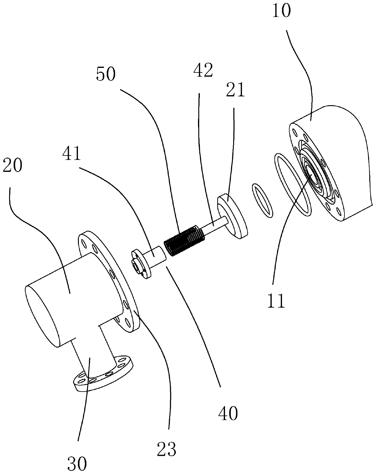
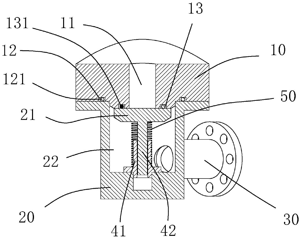
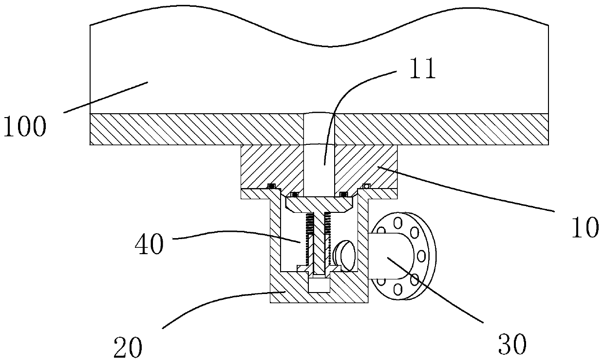
The invention discloses a pressure relief device for a high-pressure constant-volume combustion bomb. The pressure relief device comprises a pressure relief connecting cavity, a hollow pressure reliefconnecting hole is formed in the pressure relief connecting cavity, a pressure relief sleeve is axially connected with the pressure relief connecting cavity, a sliding cavity and a pressure relief opening baffle are arranged in the pressure relief sleeve, the inner diameter of the pressure relief connecting hole is smaller than the outer diameter of the pressure relief opening baffle, and a sidewall of the pressure relief sleeve is further provided with a hole connected with a pressure relief pipeline. The pressure relief device is used for connecting the combustion bomb and the pressure relief cavity; the pressure relief opening baffle blocks the pressure relief connecting hole for sealing; when the fuel is combusted, the pressure of the combustion bomb is greater than that of the pressure relief sleeve; the pressure relief opening baffle is used for opening the pressure relief connecting hole for pressure relief; when the combustion bomb exhausts to reduce the pressure to be closeto the pressure of the pressure relief sleeve, the reset spring pushes the pressure relief opening baffle to close the pressure relief connecting hole, and the pressure relief device is simple in structure, convenient to manufacture and capable of better guaranteeing the test operation safety of a double-cavity combustion bomb under the high-pressure working condition and is applied to the technical field of internal combustion engines.

Description

technical field [0001] The invention relates to the technical field of internal combustion engines, in particular to a pressure relief device for high-pressure constant-volume incendiary bombs. Background technique [0002] The combustion process of the internal combustion engine at the top dead center of combustion is completed in a very short time, which is considered to be a constant volume combustion process; while the incendiary bomb method is based on the spherical flame propagation process in a closed cavity to measure the laminar flame combustion speed, which is easy to operate , the consumption of combustible mixture is also very small, and there are few unstable structures on the flame surface due to flow, so it is very suitable for measuring the constant volume flame propagation velocity under high pressure conditions. [0003] At present, a large number of scholars in the field of combustion at home and abroad use incendiary bomb technology to study the process o...

Claims


Application Information

Patent Timeline
IPC IPC(8): G01M15/02G01M15/04G01M15/10
CPCG01M15/02G01M15/04G01M15/10
Inventor 张尊华黄勇李格升梁俊杰周梦妮
Owner WUHAN UNIV OF TECH
Why Eureka
Try Eureka