
Simulation yarn dynamic breaking strength testing equipment and testing method

A technology for breaking strength and testing equipment, which is applied in the direction of applying stable tension/pressure to test material strength, measuring devices, and strength characteristics. It can solve problems such as expensive equipment, complex equipment structure, and functional redundancy, and reduce testing. The effect of cost, simplified operation process and good mechanical properties

Active Publication Date: 2020-06-09
HUNAN INSTITUTE OF ENGINEERING
View PDF10 Cites 2 Cited by
  • Summary
  • Abstract
  • Description
  • Claims
  • Application Information

AI Technical Summary

Problems solved by technology

[0004] (1) The dynamic simulation system cannot fully describe the force that the yarn receives in actual use;
[0005] (2) Equipment is expensive due to the protection of foreign technology;
[0006](3) The equipment has complex structure and redundant functions;
[0007] (4) Due to the complexity of its operating system, it is difficult for experimental operators to collect data;
[0008] (5) Due to its redundant functions, its body is bulky and difficult to carry

Method used


Image

  • Simulation yarn dynamic breaking strength testing equipment and testing method
  • Simulation yarn dynamic breaking strength testing equipment and testing method
  • Simulation yarn dynamic breaking strength testing equipment and testing method

Examples


Embodiment Construction

[0035] The present invention will be further described below in conjunction with the accompanying drawings.

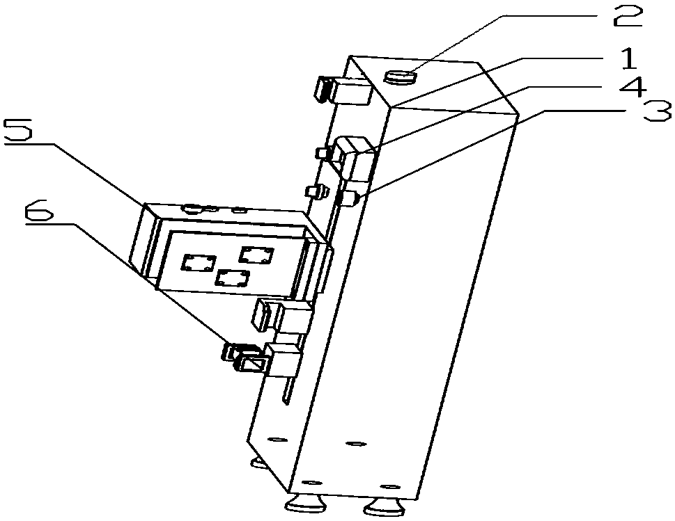
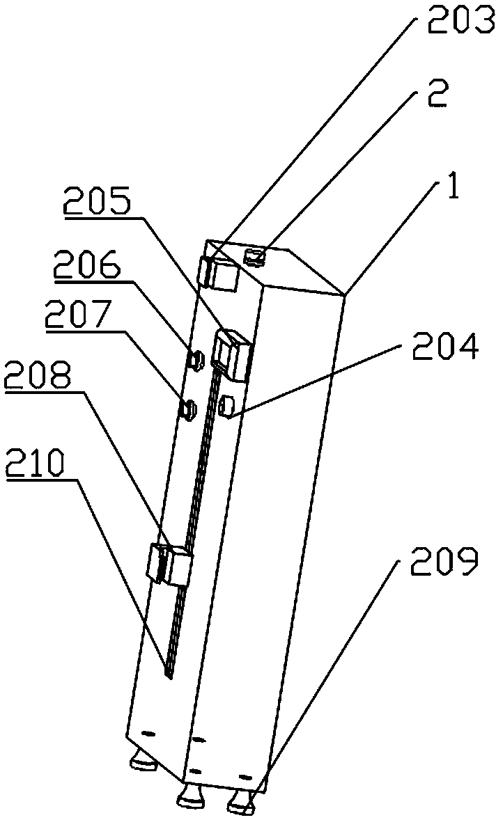
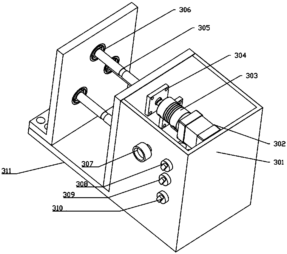
[0036] like Figure 1-4 As shown, the present invention includes a strength machine chassis 1, a microcomputer control system 4, a dynamic simulation system 5 and a yarn balancer 6. The top of the strong machine case 1 is provided with a yarn fixer 2, and the side of the strong machine case 1 is provided with a clamp 203 on the yarn, a microcomputer control system 4, a yarn stretching slideway 210, a power simulation system 5, and a yarn Lower clamp 208 and yarn balance weight 6. The yarn upper clamp 203 is located directly above the yarn stretching slideway 210; the dynamic simulation system 5 is fixedly installed on this side, and is located between the yarn upper clamp 203 and the yarn lower clamp 208. The end of the yarn lower clamp 208 is located in the yarn stretching slideway 210, and can slide along the yarn stretching slideway 210 to realize pre-tensioning a...


PUM


Abstract

The invention discloses simulation yarn dynamic breaking strength testing equipment and a testing method. The testing equipment comprises a strength machine case, a microcomputer control system, a power simulation system and a yarn balance block, a yarn fixing device is arranged at the top of the strength machine case, and an upper yarn clamp, a yarn stretching sliding way, a power simulation system, a lower yarn clamp and a yarn balance block are arranged on one side face of the strength machine case. The dynamic simulation system is fixedly arranged on the side surface and is positioned between the upper yarn clamp and the lower yarn clamp; the yarn lower clamp is located in the yarn stretching slide way and provided with a force measuring sensor. The yarn balance block is positioned below the yarn lower clamp; the power simulation system comprises a rack, a motor and a rotating shaft, the rotating shaft is connected with the output shaft of the motor, and the microcomputer control system is connected with the motor and the force transducer. According to the invention, the strength of the yarn at different angles and different rotating speeds can be tested, and the mechanical property of the fabric formed by the yarn can be simulated more accurately. The device is simple in structure, the cost is reduced, and the operation process is simplified.

Description

technical field [0001] The invention relates to a test device and a test method for dynamic breaking strength of simulated yarn. Background technique [0002] Yarn strength test is an important index to measure the quality of yarn products, and it can indirectly reflect the mechanical properties of fabrics. However, due to the complexity of the technological process in the subsequent processing of the yarn into a fabric, after the yarn is formed into a fabric, there is a certain angle between the yarn and the yarn, which causes the fabric to be affected during use. Under the action of a force of uncertain direction and magnitude, the fabric rapidly fatigues and breaks the ring. This makes it particularly important to simulate the dynamic breaking strength test of yarn. [0003] At present, the existing yarn dynamic breaking strength measurement equipment adopts the imported CTT yarn comprehensive quality evaluation system, which can measure the dynamic friction coefficient...

Claims


Application Information

Patent Timeline
Patent Type & Authority Applications(China)
IPC IPC(8): G01N3/08G01N3/04G01N3/06
CPCG01N3/08G01N3/04G01N3/066G01N2203/0017G01N2203/0067G01N2203/028G01N2203/0411G01N2203/0423G01N2203/0617G01N2203/0676
Inventor 周衡书席立锋周忠成武世锋
Owner HUNAN INSTITUTE OF ENGINEERING
Learn More