
Perovskite solar cell module and packaging method thereof

A technology of solar cells and encapsulation methods, applied in the direction of electrical components, electric solid devices, circuits, etc., can solve the problems of thicker and wider, and achieve the effects of enhanced encapsulation, good water blocking effect, and easy replacement

Pending Publication Date: 2020-06-09
SHANGHAI INST OF CERAMIC CHEM & TECH CHINESE ACAD OF SCI +2
View PDF1 Cites 1 Cited by
  • Summary
  • Abstract
  • Description
  • Claims
  • Application Information

AI Technical Summary

Problems solved by technology

The single cell module in the perovskite solar cell module can be easily replaced, thereby solving the problem that if a single perovskite cell module is damaged during use, it will affect the power generation performance of the overall module, and the structure of the present invention has only one substrate at the bottom, and does not require Fill the surrounding area with additional adhesive film, and because the thickness of the battery itself is only micron level after removing the glass substrate, only one layer of filling layer (thickness 0.4~0.6mm) needs to be set between the battery sheet and the substrate, which solves the problem in the existing module structure Problems requiring thicker and wider fill layer material with better water blocking effect

Method used


Image

  • Perovskite solar cell module and packaging method thereof
  • Perovskite solar cell module and packaging method thereof
  • Perovskite solar cell module and packaging method thereof

Examples


Embodiment 1

[0066] Such as Figure 1~3 As shown, this embodiment relates to a parallel perovskite solar cell module. The specific implementation steps include:

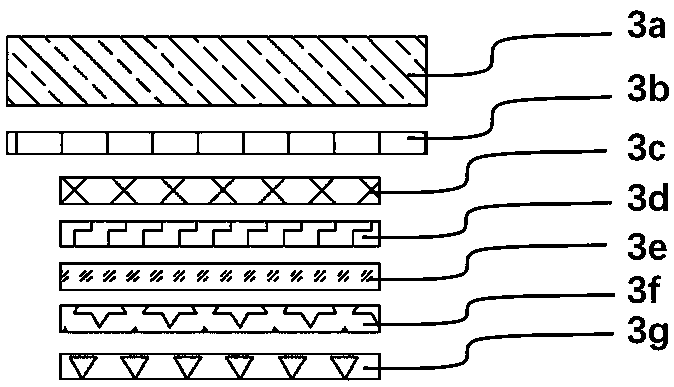
[0067] The perovskite solar cell modules arranged in 2 rows and 4 columns are laid on the tempered glass (bottom substrate 1). A transparent substrate 3a with a transparent conductive layer 3b formed on the lower surface is provided on the perovskite solar cell module. A single perovskite solar cell module includes from top to bottom: a hole blocking layer 3c, an electron transport layer 3d, a perovskite light absorbing layer 3e, a hole transport layer 3f, and a counter electrode layer 3g; wherein, the transparent conductive layer 3b is provided with There is a total electrode 5, which is used as the positive and negative terminals of a single perovskite battery module. A filling layer 2 is laid between a single perovskite solar cell module and the bottom substrate 1 , and encapsulation glue 4 is laid around the single perovsk...

Embodiment 2

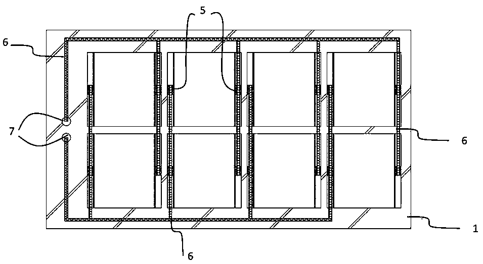
[0071] Such as Figure 5~8 As shown, this embodiment relates to a tandem perovskite solar cell module. The specific implementation steps include:

[0072] When the first row of perovskite solar cell modules are placed, the direction of positive and negative poles is the left side is the negative pole, and the right side is the positive pole; when the second row of perovskite solar cell modules is placed, the direction of the positive and negative poles is the left side is the positive pole , the right side is negative.

[0073] Use conductive copper tape (connecting wire 6) to connect the positive and negative electrodes of the perovskite solar power module laid above, and follow the Figure 7 The perovskite solar cell arrays are connected in series in the same way; after the series connection, the positive and negative electrodes are collected at one end of the tempered glass respectively, and the positive and negative electrodes are respectively passed through the through ...

Embodiment 3

[0076] MAPbI 3 Packaging of perovskite solar cell modules, wherein the perovskite solar cell module contains multiple unit cells, and each unit cell includes an FTO layer (transparent conductive layer 3b), hole blocking layer 3c, electron transport layer 3d, MAPbI 3 Perovskite layer (perovskite light-absorbing layer 3e), hole transport layer 3f, carbon counter electrode layer (counter electrode layer 3g), wherein, MAPbI 3 The perovskite layer is arranged between the electron transport layer and the carbon counter electrode layer; the FTO layers of adjacent unit cells are separated by etching lines, and the counter electrode layer is connected to the FTO layers of adjacent unit cells across the etching lines to achieve 8 The cells are connected in series.

[0077] The perovskite solar cell modules arranged in 2 rows and 2 columns are laid on the tempered glass (bottom substrate 1). A single perovskite solar cell module contains 8 unit cells connected in series, and the positi...


PUM

PropertyMeasurementUnit
thicknessaaaaaaaaaa
thicknessaaaaaaaaaa
widthaaaaaaaaaa

Abstract

The invention provides a perovskite solar cell module and a packaging method thereof. The cell module comprises a bottom substrate, a plurality of perovskite solar cell modules which are connected inseries and in parallel and are arranged on the bottom substrate in a matrix manner, a peripheral packaging adhesive arranged at the periphery of each perovskite solar cell module, and a transparent substrate covering the perovskite solar cell modules, wherein a transparent conductive layer in sealed connection with the peripheral packaging adhesive is formed on the lower surface of the transparentsubstrate, so that each perovskite solar cell module is sealed in a packaging space defined by the bottom substrate, the transparent substrate and the peripheral packaging adhesive. Positive and negative connecting terminals of each cell are arranged outside the packaging adhesive on the four sides of each cell, so that series-parallel connection between the adjacent cells is realized, and independent packaging of each cell is realized at the same time, so that the packaging effect of the single cell can be enhanced, the overall packaging effect is good, and the single cell can be independently replaced when a fault occurs.

Description

technical field [0001] The invention relates to the field of photovoltaic technology, in particular to a perovskite solar cell module and a packaging method thereof. Background technique [0002] Since the invention of perovskite solar cells in 2009, based on the advantages of abundant earth reserves, simple preparation process, and high conversion efficiency, it has attracted extensive attention from researchers and industries in the field of solar power generation technology around the world, making it possible to realize cheap solar power generation. The core technology fully reflects its good commercialization prospects and great potential market value. However, the stability and device size scaling of perovskite solar cells have been the key problems restricting their high-efficiency commercial applications. At present, substantial progress has been made in the preparation technology of large-scale perovskite cells. However, in order to further prepare large-scale pero...

Claims


Application Information

Patent Timeline
Patent Type & Authority Applications(China)
IPC IPC(8): H01L51/44H01L51/48
CPCH10K30/80H10K30/88Y02E10/549
Inventor 杨松旺陈薪羽寿春晖陈宗琦金胜利黄绵吉沈曲郑渭建赵金龙孙树忠陈春峰
Owner SHANGHAI INST OF CERAMIC CHEM & TECH CHINESE ACAD OF SCI
Learn More