Circularly polarized antenna

A circularly polarized antenna, dielectric substrate technology, applied in the directions of antenna, antenna coupling, antenna grounding device, etc., can solve the problem of not being able to take into account the axial ratio bandwidth and impedance bandwidth at the same time, and not being able to meet the circularly polarized high gain design. Cross-polarization level, good grounding, effect of increasing gain

Inactive Publication Date: 2020-06-09
DONGHUA UNIV
View PDF3 Cites 3 Cited by
  • Summary
  • Abstract
  • Description
  • Claims
  • Application Information

AI Technical Summary

Problems solved by technology

[0004] The problem to be solved by the present invention is: the traditional method of increasing gain cannot take into account the

Method used


Image

  • Circularly polarized antenna
  • Circularly polarized antenna
  • Circularly polarized antenna

Examples


Embodiment Construction

[0032] In order to make the present invention more comprehensible, preferred embodiments are described in detail below with accompanying drawings.

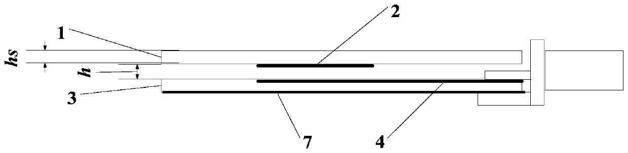
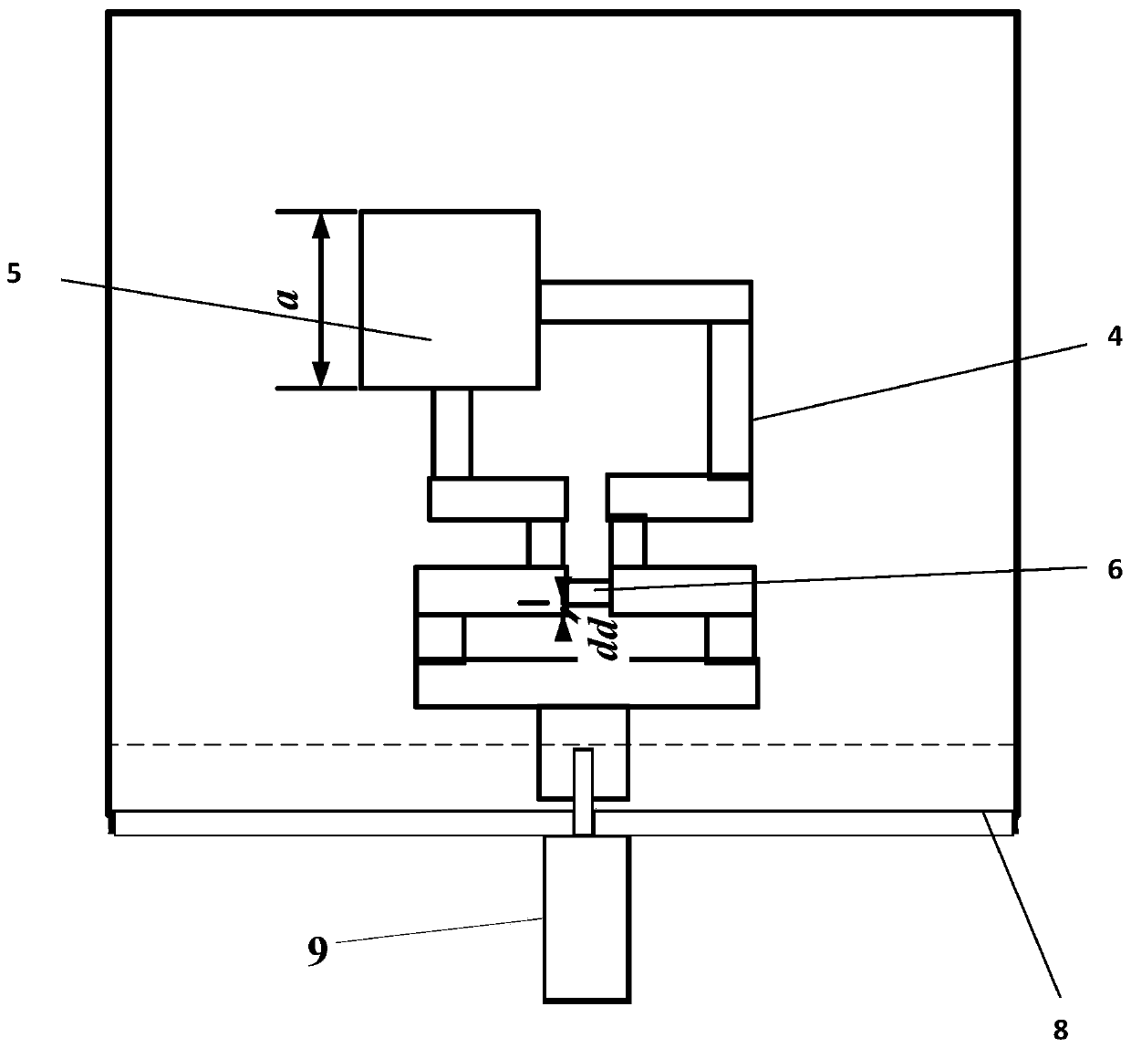
[0033] like figure 1 and 2 As shown, the present invention provides a circularly polarized antenna, including an upper dielectric substrate 1, a parasitic patch 2, a lower dielectric substrate 3, a Wilkinson power divider feed network 4, a radiation patch 5, an isolation resistor 6, Ground plate 7, metal ground outer wall 8 and SMA connector 9. The upper dielectric substrate 1 and the lower dielectric substrate 3 are stacked up and down, the upper dielectric substrate 1 is installed with a parasitic patch 2 on the lower surface, and the lower dielectric substrate 3 is installed with a radiation patch 5 and a Wilkinson power divider feed network 4 on the lower surface. The grounding plate 7 is installed, the shunt port of the Wilkinson power divider feed network 4 is connected to the radiation patch 5, and the SMA connector 9 pas...


PUM

PropertyMeasurementUnit
Plate thicknessaaaaaaaaaa

Abstract

The invention provides a circularly polarized antenna. The antenna comprises an SMA connector, an upper dielectric substrate and a lower dielectric substrate, wherein the upper dielectric substrate and the lower dielectric substrate are arranged in a stacked manner; a parasitic patch is arranged on the lower surface of the upper dielectric substrate; a radiation patch and a Wilkinson power dividerfeed network are arranged on the upper surface of the lower dielectric substrate; a grounding plate is arranged on the lower surface of the lower dielectric substrate; the shunt port of the Wilkinsonpower divider feed network is connected with the radiation patch; the combination port of the Wilkinson power divider feed network is connected with the SMA connector so as to realize side feed, andtherefore, circularly polarized wave radiation is achieved; and the upper dielectric substrate partially projects and reflects radiation waves, so that waves on the outer side of the upper dielectricsubstrate are superposed in an in-phase manner. According to the circularly polarized antenna of the invention, the laminated structure with the additional parasitic patch is adopted, so that the radiation efficiency of the antenna is improved, and the antenna gain is improved; the antenna is simple in structure, achieves a circular polarization radiation mode, is low in profile, is easy to form an array, and can be widely used in communication systems such as satellites and radars.

Description

technical field [0001] The invention relates to a circularly polarized antenna, in particular to a microstrip antenna used in Ku-band high-gain mobile communication. Background technique [0002] With the increasingly complex electromagnetic environment, the wireless communication system puts forward higher requirements on the performance of the antenna as the core equipment. When the linearly polarized wave is reflected by obstacles during propagation, polarization polarization and multipath effects will occur, and the receiving level of the antenna will drop sharply, making it difficult to guarantee the communication quality. In contrast, circularly polarized waves can overcome the level fading caused by polarization polarization, and the special polarization mode of circular polarization makes circularly polarized antennas have strong anti-interference ability. The microstrip antenna has the advantages of small size, light weight, and easy shaping, and various structures...

Claims


Application Information

Patent Timeline
IPC IPC(8): H01Q1/38H01Q1/48H01Q1/50H01Q15/24H01Q1/52
CPCH01Q1/38H01Q1/48H01Q1/50H01Q1/52H01Q15/24
Inventor 徐超单志勇徐好好
Owner DONGHUA UNIV
Why Eureka
Try Eureka