Reverse-axis tension active control system for sectional warping machine

An active control system and the technology of the section warping machine, which is applied in the field of textile machinery, can solve the problems of incomplete conversion and large extra energy consumption, and achieve the effect of stable control and small extra loss

Active Publication Date: 2020-06-12
江阴市四纺机新科技制造有限公司
View PDF11 Cites 0 Cited by
  • Summary
  • Abstract
  • Description
  • Claims
  • Application Information

AI Technical Summary

Problems solved by technology

In addition, the conversion of mechanical energy into internal energy also means that the energy output by the motor is not completely converted into the kinetic energy of the warp beam and yarn, and the additional energy consumption is relatively large

Method used


Image

  • Reverse-axis tension active control system for sectional warping machine
  • Reverse-axis tension active control system for sectional warping machine
  • Reverse-axis tension active control system for sectional warping machine

Examples


Embodiment 1

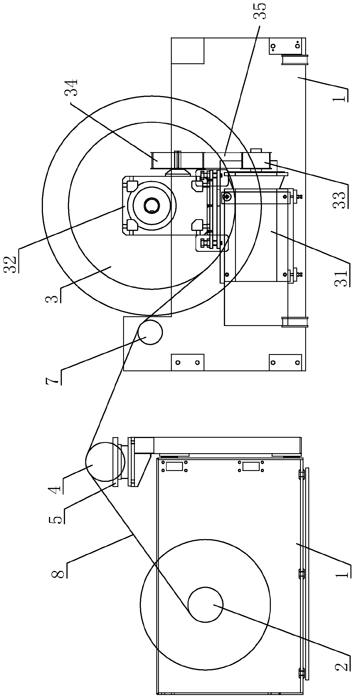
[0035] An active control system of inverted axis tension for section warping machines, such as figure 1 As shown, it includes a frame 1, on which a guide roller 3, a guide roller 7, a tension roller 4 and a warp beam 2 are erected successively on the frame 1, and the above-mentioned structures are all connected with the frame 1 in rotation, along the direction of travel of the yarn 8 aligned and parallel to each other.

[0036] Such asfigure 1 As shown, a motor assembly is erected on the frame 1 , including a first motor 31 and a reducer 32 . Wherein, the output shaft of the first motor 31 is provided with a driving pulley 33, the input shaft of the reducer 32 is provided with a driven pulley 34, and the driving pulley 33 and the driven pulley 34 are wound with a transmission belt. 35, the output shaft of speed reducer 32 then links to each other with guide roller 3. The motor assembly drives the yarn guide roller 3 to rotate, and controls the speed at which the yarn guide r...

Embodiment 2

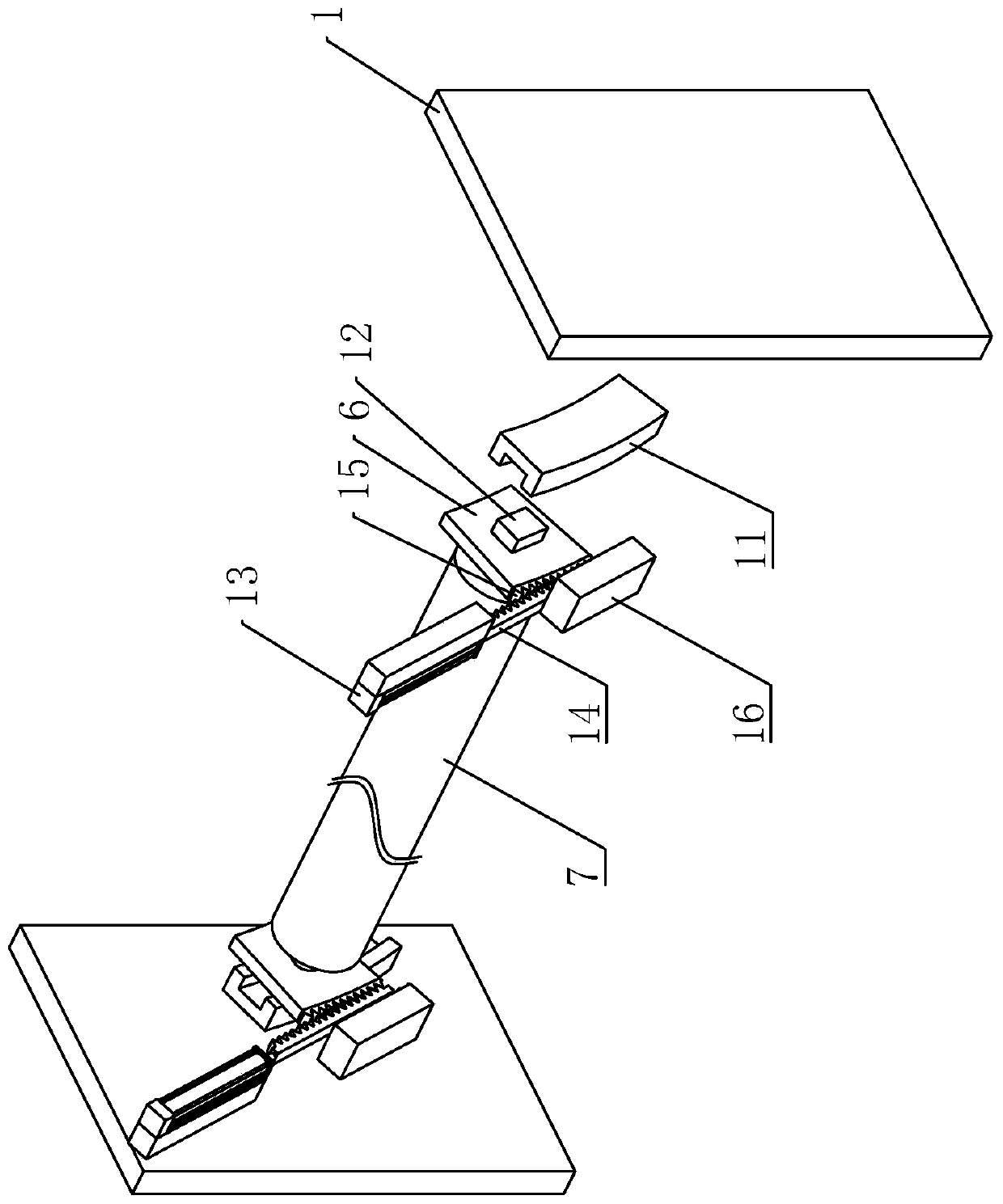
[0049] The difference from Embodiment 1 is that the driving assembly that drives the adjustment seat 6 to slide is different, such as Figure 4 As shown, the frame 1 is mounted with a screw 19 and a second motor 111 . The screw rod 19 is arranged along the tangential direction of the slide rail 11 , is connected in rotation with the frame 1 , is connected with the output shaft of the second motor 111 , and rotates under the drive of the second motor 111 . In addition, the screw rod 19 is sleeved with a shifting block 18, and the two are screwed together. One end of the shifting block 18 facing the center of the slide rail 11 is provided with a draw slot 110 , and the draw slot 110 is arranged along the normal direction of the slide rail 11 . Correspondingly, a shift lever 61 is welded on the adjustment seat 6 . The driving rod 61 is parallel to the guide roller 7 and is installed in the slot 110 , and its diameter is equal to the width of the slot 110 .

[0050] Such as F...


PUM


Abstract

The invention belongs to the technical field of textile machinery, and discloses a reverse-axis tension active control system for a sectional warping machine. The key points of the technical scheme are that the reverse-axis tension active control system comprises a rack, wherein a warp beam and a yarn guide roller are rotationally erected on the rack; a motor assembly used for driving the yarn guide roller to rotate is also erected on the rack; the reverse-axis tension active control system also comprises a tension roller erected between the warp beam and the yarn guide roller; the tension roller is rotationally connected with the rack; the height of the tension roller is greater than that of the warp beam and the yarn guide roller; the tension roller is parallel to the warp shaft; a tension sensor is arranged below the tension roller, and the tension sensor is connected with the rack; and the tension sensor is electrically connected with the motor assembly. The reverse-axis tension active control system has the effects that the rotating speed of a motor can be adjusted according to the yarn tension, the energy output by the motor is fully utilized as much as possible in the process of controlling the tension of the yarn, and the additional loss is small.

Description

technical field [0001] The invention relates to the technical field of textile machinery, in particular to an active control system for an inverted axis tension used in a section warping machine. Background technique [0002] Warping is to wind the bobbins on the pan head in parallel, constant speed and neatly under the same tension according to the number and length of the yarns required by the process. It is a crucial preparation process in warp knitting. A warping machine is required for this process. [0003] The Chinese patent with the notification number CN202175773U discloses a split-shaft warping machine, including a main frame mechanism; a shaft setting mechanism; a drying mechanism; a telescopic reed mechanism; Yarn pressing mechanism; upper and lower shaft mechanism; the upper yarn of the unwinding pan head is dried by the drying cylinder, then fixed by the telescopic reed, passed through the speed measuring guide roller, and then evenly wound on another pan head...

Claims


Application Information

Patent Timeline
IPC IPC(8): D02H5/00D02H13/26
CPCD02H5/00D02H13/26
Inventor 徐曙万鹤俊
Owner 江阴市四纺机新科技制造有限公司
Why Eureka
Try Eureka