Refiner disc, refiner rotor and refiner with such refiner disc

A refiner and grinding disc technology, applied in pulp beating/refining methods, electromechanical devices, mechanical energy control, etc., to achieve the effects of high paper product strength, small size, and reduced investment costs

Active Publication Date: 2022-06-21
ANDRITZ CHINA
View PDF0 Cites 0 Cited by
  • Summary
  • Abstract
  • Description
  • Claims
  • Application Information

AI Technical Summary

Problems solved by technology

However, even the best manufacturing methods have some limitations

Method used


Image

  • Refiner disc, refiner rotor and refiner with such refiner disc
  • Refiner disc, refiner rotor and refiner with such refiner disc
  • Refiner disc, refiner rotor and refiner with such refiner disc

Examples


no. 1 example

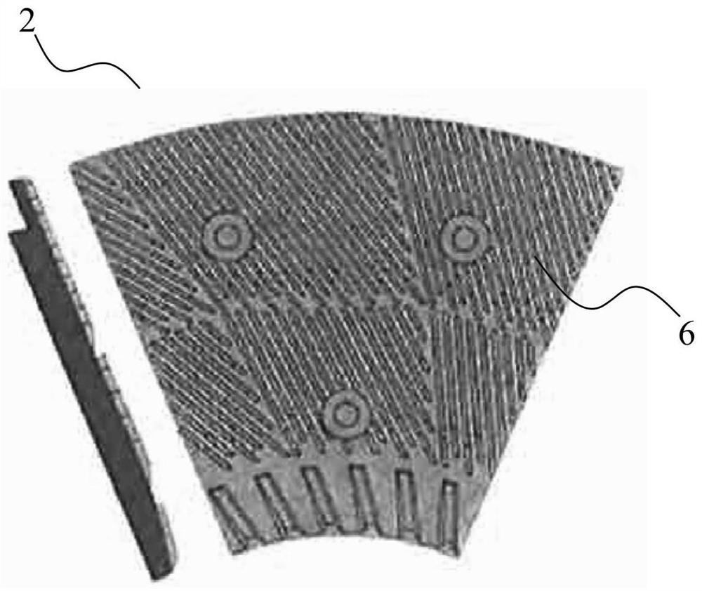
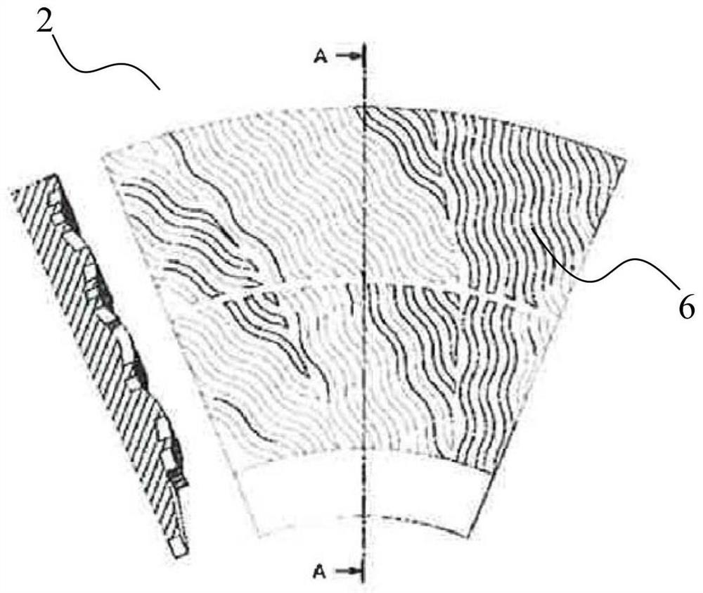
[0023] According to a first embodiment of the invention, at least part of the sharpening edges of the refiner disc are designed to be wavy in the radial direction, and at least part of the sharpening edges of the refiner disc are designed to be wavy in the axial direction. Wherein, the wavy degree of the grinding edge of the refiner disc in the radial direction gradually increases from the slurry inlet side in the center of the refiner disc to the slurry outlet side at the outer periphery of the refiner disc. Preferably, the ratio of the degree of corrugation in the radial direction of the sharpening edges of the refiner discs is between 1:1.15 and 1:1.45 at the pulp inlet side at the centre of the disc and at the pulp outlet side at the outer periphery of the disc.

[0024] According to a second embodiment of the invention, at least part of the sharpening edges of the refiner disc are designed to be wavy in the radial direction, and at least part of the sharpening edges of the...


PUM


Abstract

The invention relates to a refiner disc, characterized in that at least part of the sharpening edges of the refiner disc are designed to be undulating in the radial direction and at least part of the sharpening edges of the refiner disc are designed to be wavy in the axial direction Into a wavy shape. The present invention aims at increasing the sharpening length by corrugating the flow channel in the radial direction as well as in the axial direction. This enables a considerable increase in the length of the grinding edge, which enables a reduction in the diameter of the grinding disc and thus reduces the no-load power.

Description

technical field [0001] The present invention relates to refiner discs and refiner rotors. In addition, the present invention also relates to a refiner having the refiner disc. The refiner discs relate to disc discs, conical discs and cylindrical discs. Background technique [0002] Refining is used in essentially all paper mills worldwide and it is one of the most energy-intensive process stages in a paper mill. In the best interest of all customers, the energy consumption for refining should be reduced and still maintain the desired fiber properties. Low-consistency refining of fiber stock suspensions is a common practice for improving fiber properties and strength, including chemical pulping, mechanical pulping, and fiber recovery. There are various disc patterns on the market, especially for the most commonly used type of double disc refiner. The loading (for reducing the gap between the discs) is used to apply the required refining energy to achieve specific fiber pr...

Claims


Application Information

Patent Timeline
Patent Type & Authority Patents(China)
IPC IPC(8): D21D1/30H02K7/14
CPCD21D1/303D21D1/306H02K7/14
Inventor 亚历山大·葛帅德
Owner ANDRITZ CHINA
Why Eureka
Try Eureka