Terahertz wavefront phase control device based on liquid crystal and wire-grid metasurface

A metasurface and control device technology, applied in nonlinear optics, instruments, optics, etc., can solve problems such as limiting practical applications, high applied voltage, and slow modulation rate of devices

Active Publication Date: 2021-07-16
TSINGHUA UNIV
View PDF19 Cites 0 Cited by
  • Summary
  • Abstract
  • Description
  • Claims
  • Application Information

AI Technical Summary

Problems solved by technology

However, the distance between electrodes used to apply voltage to liquid crystals is on the order of hundreds of microns.
These problems will bring constraints such as slow modulation rate and high applied voltage of the devices, which in turn limit their practical applications.

Method used


Image

  • Terahertz wavefront phase control device based on liquid crystal and wire-grid metasurface
  • Terahertz wavefront phase control device based on liquid crystal and wire-grid metasurface
  • Terahertz wavefront phase control device based on liquid crystal and wire-grid metasurface

Examples


Embodiment 1

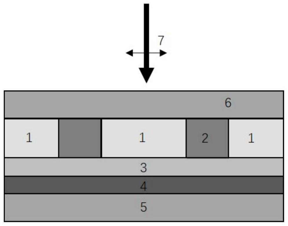
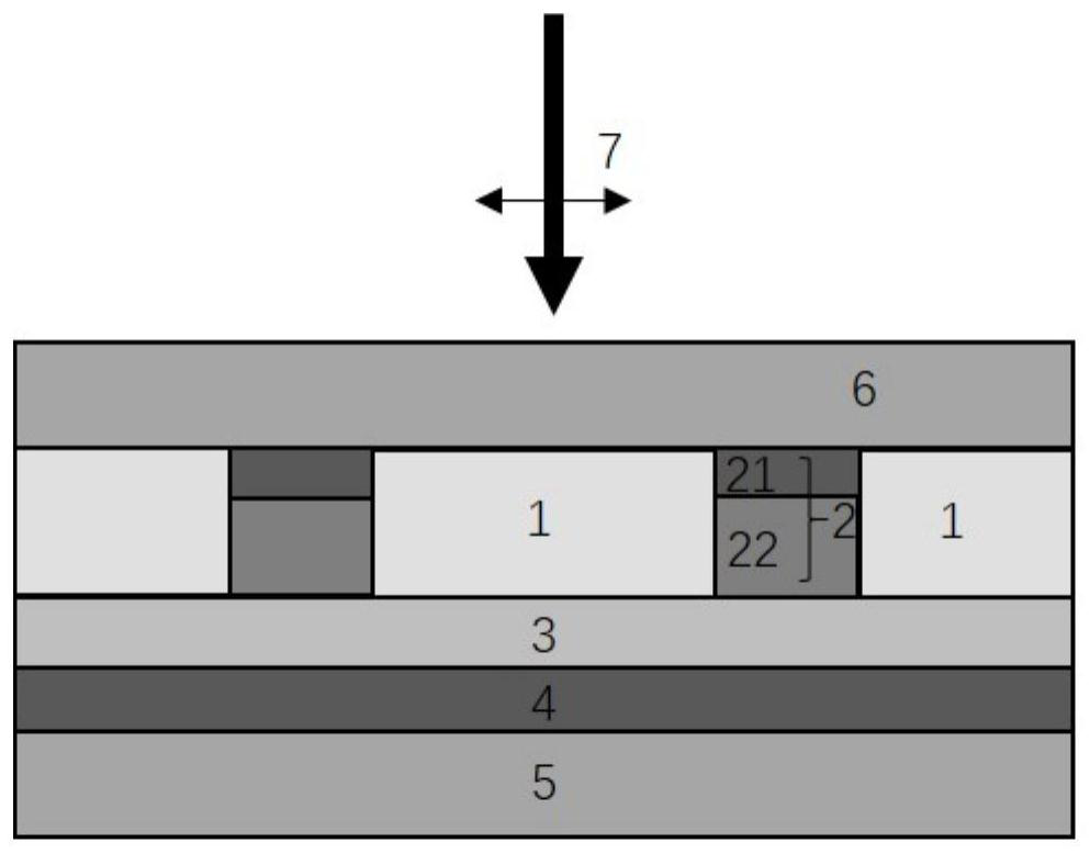
[0030] In the first implementation example, the operating frequency of the phase modulator is 0.5 THz. Such as image 3 As shown, the liquid crystal material selected for the liquid crystal 1 is E7, and when the applied voltage is 0-15V, the refractive index change in the terahertz band is about 1.55-1.7. Gold is selected as the constituent material of the reflector 4, and its thickness is 100 nanometers. Al2O3 is selected as the material for the dielectric isolation layer 3 with a thickness of 200 nanometers. The metasurface electrode 2 selects silicon and gold as the composite layer of the constituent materials, the gold thickness of the conductive layer 21 is 100 nanometers, and the silicon doping concentration in the single layer 22 that is transparent to the application band and can be made of conductive materials is 1.4×10 14 A single layer 22 has a thickness of 130 microns per cubic centimeter. The wire-grid metasurface electrode 2 adopts such as Figure 4 For the i...

Embodiment 2

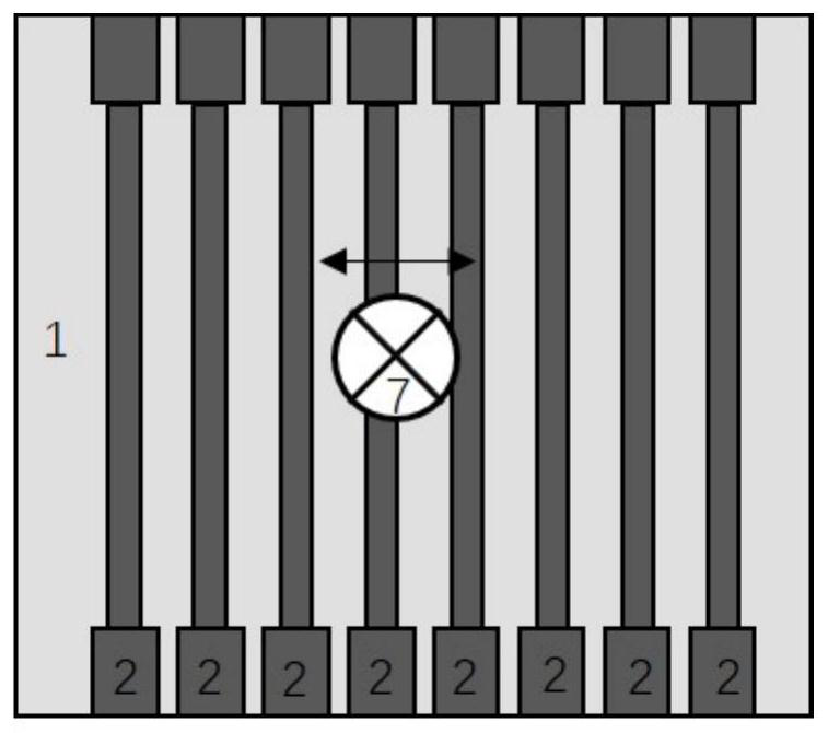
[0031] In the second implementation example, the working frequency of the phased array is 0.5 THz. The basic structure is as figure 2 , image 3 shown. The structure of the wire-grid metasurface electrode 2 and the way of applying voltage are as follows: Figure 9 As shown, each gate is independent of each other, and the voltage difference between adjacent gates can be independently controlled, and other configurations are consistent with the configuration of the phase modulator in the first implementation example. Such as Figure 10 As shown, since the voltage difference between adjacent gates can be independently controlled, through the device of this implementation example, the reflected terahertz beam 8 formed after the incident terahertz electromagnetic beam 7 with a set frequency in the p-polarization direction is reflected by the device can be Each pair of gates has the same gradient phase difference In turn, the beams reflected by adjacent grids produce wave pat...


PUM

PropertyMeasurementUnit
thicknessaaaaaaaaaa
thicknessaaaaaaaaaa
thicknessaaaaaaaaaa

Abstract

The present invention proposes a terahertz wavefront phase control device based on liquid crystals and wire-grid metasurfaces, including substrates, mirrors, and dielectric isolation layers stacked sequentially from bottom to top, and composed of wire-grid metasurface electrodes The metasurface structure layer formed by pouring liquid crystals between adjacent grids and the transmission medium layer, the terahertz electromagnetic beam with the frequency set in the p-polarization direction is injected from the transmission medium layer; when the metasurface electrode is connected to an external voltage, the The direction of the voltage applied by the liquid crystal is orthogonal to the transmission direction of the terahertz electromagnetic beam. Among them, the spaced grids in the metasurface electrode are connected in series to form an interdigitated array electrode, and each spaced grid is connected to the same applied voltage; Applied voltage for each gate. The invention applies a voltage orthogonal to the transmission direction of the terahertz electromagnetic beam to the liquid crystal, and realizes the wave front phase control of the terahertz electromagnetic beam at an appreciable modulation rate.

Description

technical field [0001] The invention can be applied to fields related to phase modulation of electromagnetic waves in the terahertz band, and more specifically, relates to a terahertz wavefront phase control device based on liquid crystal and wire-grid metasurfaces. Background technique [0002] In the application field of terahertz wave technology, it is of great significance for many terahertz wave applications to quickly and efficiently modulate information such as the intensity and phase of terahertz wave signals at the micro-nano scale. Metasurface refers to an electromagnetic antenna array composed of subwavelength structures. At the mesoscopic scale, through the reasonable design of the shape and arrangement of the optical antenna, the metasurface can effectively control the amplitude, phase and polarization of electromagnetic waves in a two-dimensional plane, breaking through the limitations of traditional electromagnetic laws, and realizing Effective tailoring of e...

Claims


Application Information

Patent Timeline
Patent Type & Authority Patents(China)
IPC IPC(8): G02F1/13G02F1/1343G02F1/01
CPCG02F1/01G02F1/0136G02F1/13G02F1/134309G02F2203/13G02F2203/50
Inventor 杨原牧陈赛
Owner TSINGHUA UNIV
Why Eureka
Try Eureka