

Variable-temperature spectrum testing device
A spectrum testing and temperature control device technology, applied in the field of optical measurement, can solve problems such as large testing requirements, and achieve the effects of improving testing speed, accurate measurement results, and simple structure
- Summary
- Abstract
- Description
- Claims
- Application Information
AI Technical Summary
Problems solved by technology
Method used
Image

Examples
Embodiment 1
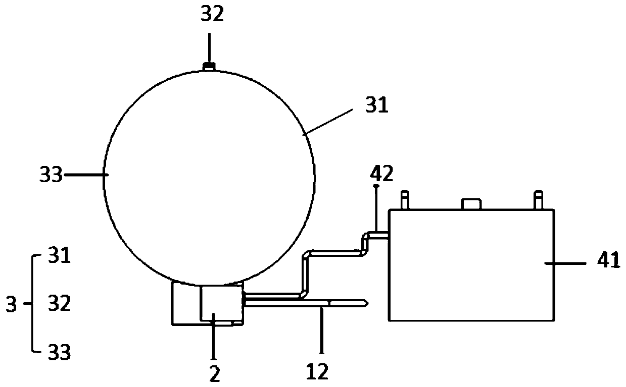
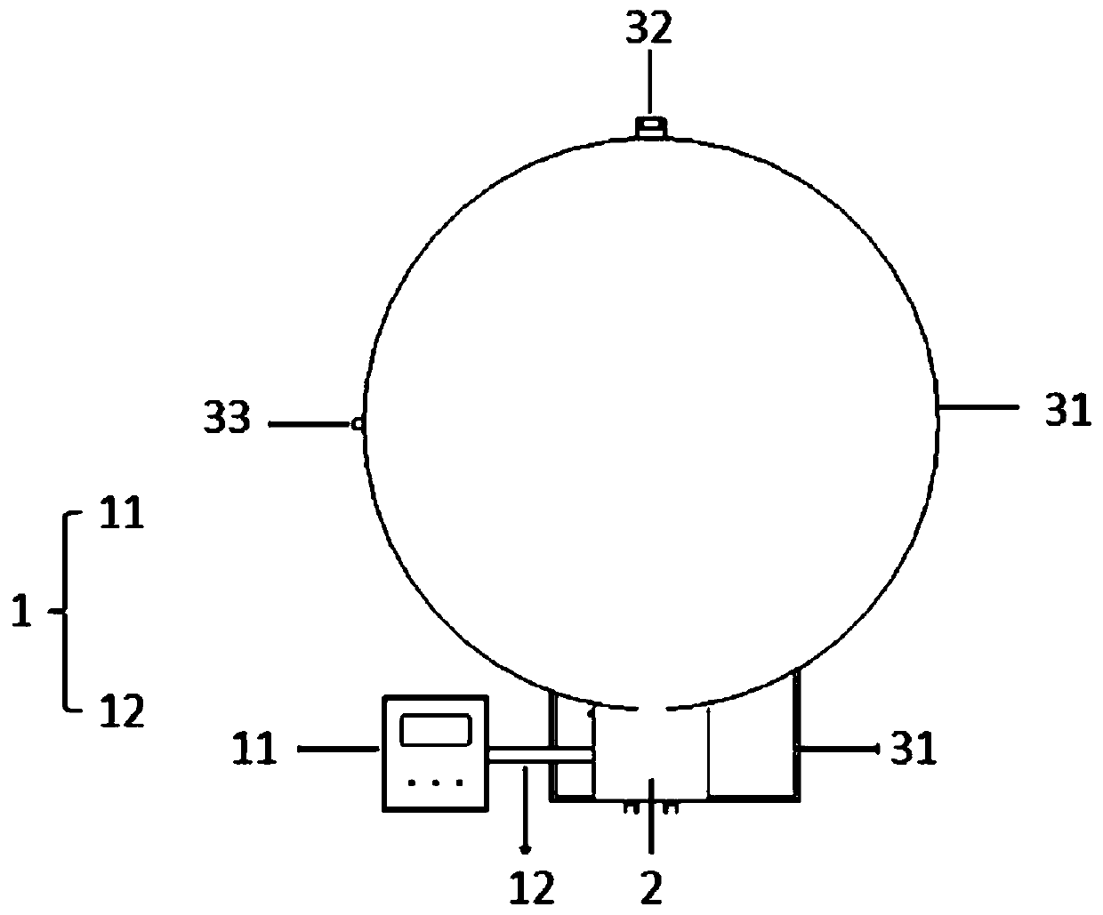
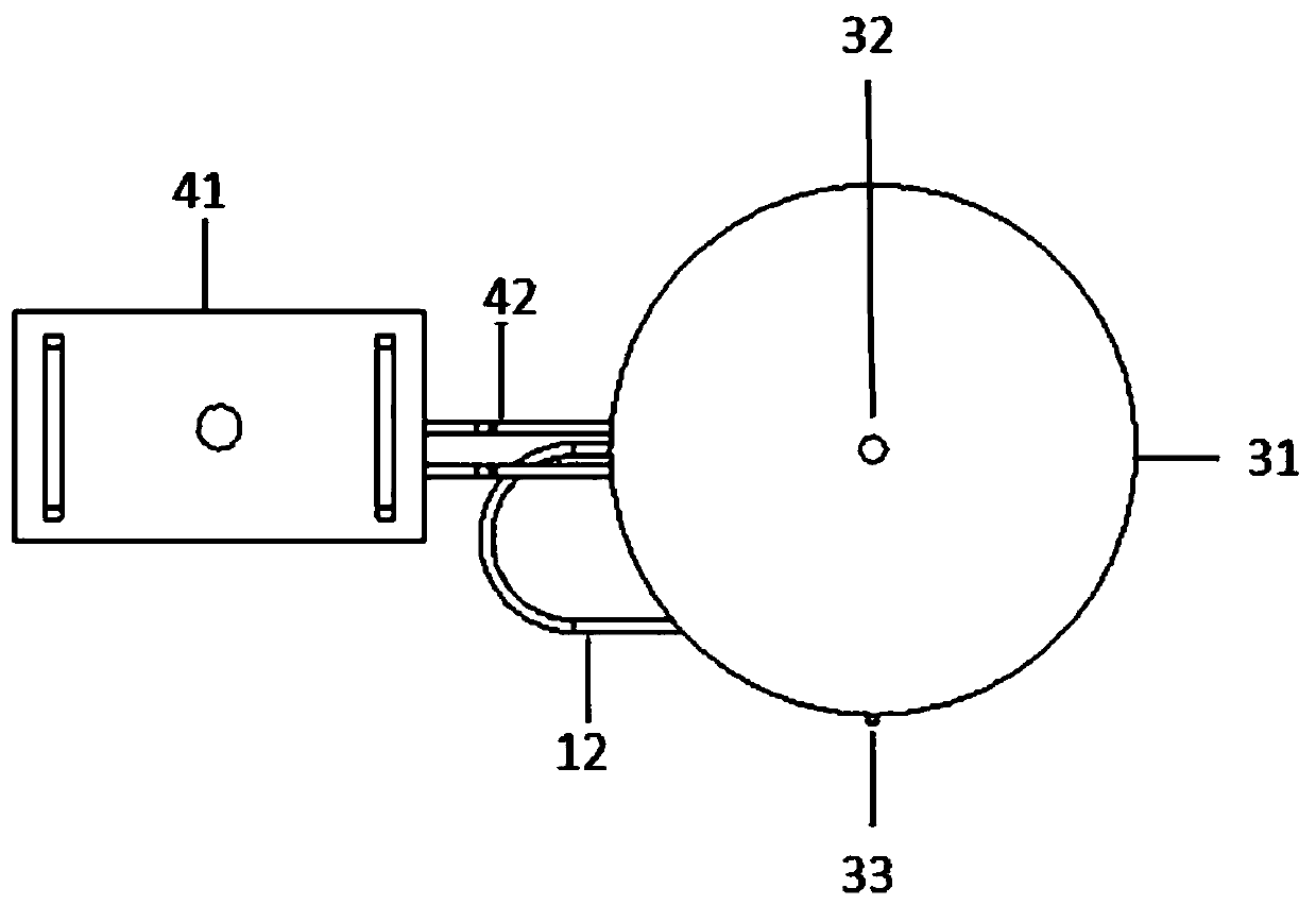
[0038] see Figure 1 to Figure 6 As shown, the present invention provides a kind of variable temperature spectrum testing device, comprises operating system 1, variable temperature system 2, measurement system 3, cooling system 4 and analysis system (not shown in the figure);
[0039] The operating system 1 includes a system console 11 and a data transmission line 12. The system console 11 is used to set the test temperature. In this embodiment, the range of the test temperature set by the system console 11 is -30°C to 150°C. The input end is connected with the system console 11, and the data transmission line 12 is used to transmit the test temperature data set by the system console 11;
[0040] see Figure 5 As shown, the variable temperature system 2 includes a variable temperature stage 21 and a temperature control device (because the temperature control device is arranged inside the temperature variable system 2, it is not shown in the figure), and the variable temperatu...
Embodiment 2
[0050] The optical performance parameters of the temperature-variable optical material are tested by using a temperature-variable spectrum testing device provided in Embodiment 1, and the steps are as follows:
[0051] 1) Weigh 100 mg of YAG yellow fluorescent powder and evenly spread it on the variable temperature stage 21;
[0052] 2) The measurement temperature is set through the system console 11, the measurement temperature is set to -10°C, the semiconductor refrigerating sheet of the semiconductor thermoelectric cooling chip works, and the variable temperature stage 21 is controlled to cool down to -10°C;
[0053] 3) Push the variable temperature stage 21 to the lower end of the integrating sphere 31, and close the integrating sphere 31 after the temperature of the variable temperature stage 21 is stable;
[0054] 4) Turn on the COB blue light source, whose excitation wavelength is 450nm;
[0055] 5) Turn on the computer for measurement, and the measured result is: the ...
Embodiment 3
[0059] The optical performance parameters of the temperature-variable optical material are tested by using a temperature-variable spectrum testing device provided in Embodiment 1, and the steps are as follows:
[0060] 1) Prepare a fluorescent film with a thickness of 2 mm and evenly spread it on the variable temperature stage 21;
[0061] 2) The measurement temperature is set through the system console 11, the measurement temperature is set to -10°C, the semiconductor refrigerating sheet of the semiconductor thermoelectric cooling chip works, and the variable temperature stage 21 is controlled to cool down to -10°C;
[0062] 3) Push the variable temperature stage 21 to the lower end of the integrating sphere 31, and close the integrating sphere 31 after the temperature of the variable temperature stage 21 is stable;
[0063] 4) Turn on the COB blue light source, whose excitation wavelength is 450nm;
[0064] 5) Turn on the computer for measurement, and the measured result is...
PUM
| Property | Measurement | Unit |
|---|---|---|
| Beam angle | aaaaa | aaaaa |
| Radius size | aaaaa | aaaaa |
Abstract
Description
Claims
Application Information