
A kind of peeling and sorting equipment

A technology of equipment and modules, applied in the field of mechanical processing, can solve the problems of manufacturers' troubles, affect productivity, low efficiency, etc., and achieve the effect of strengthening market competitiveness, ensuring transmission efficiency, and ensuring work efficiency.

Active Publication Date: 2021-12-28
深圳市高旗自动化技术有限公司
View PDF7 Cites 0 Cited by
  • Summary
  • Abstract
  • Description
  • Claims
  • Application Information

AI Technical Summary

Problems solved by technology

However, since the fastest response time of the cylinder is 0.4S, and the conveying speed of the peeling sorting equipment can reach 0.26S / piece, that is, the response time of the bad row mechanism is greater than the conveying speed of the peeling sorting device, so that it will drag Slow down the working efficiency of the whole stripping and sorting equipment, affecting productivity
[0005] However, the peeling and sorting equipment in the prior art is to transfer the protective film one by one after selecting the good product protective film, and the maximum conveying speed of the peeling and sorting equipment can reach 0.26S / piece, its conveying speed is fast, and the conveyor belt needs Doing it for a long time can extend the transmission time and facilitate the later picking of materials. Although it can ensure efficiency, it will greatly increase the occupied area and is not conducive to improving market competitiveness; if the length of the conveyor belt is not extended, more staff will be required Although sorting can ensure efficiency, it will increase labor costs and is not conducive to improving market competitiveness; or reduce the transmission speed of stripping and sorting equipment, but it will lead to low efficiency and is not conducive to improving market competitiveness. Therefore, Great trouble for manufacturers

Method used


Image

  • A kind of peeling and sorting equipment
  • A kind of peeling and sorting equipment
  • A kind of peeling and sorting equipment

Examples


Embodiment Construction

[0037] The present invention will be further described below in conjunction with specific embodiments and accompanying drawings.

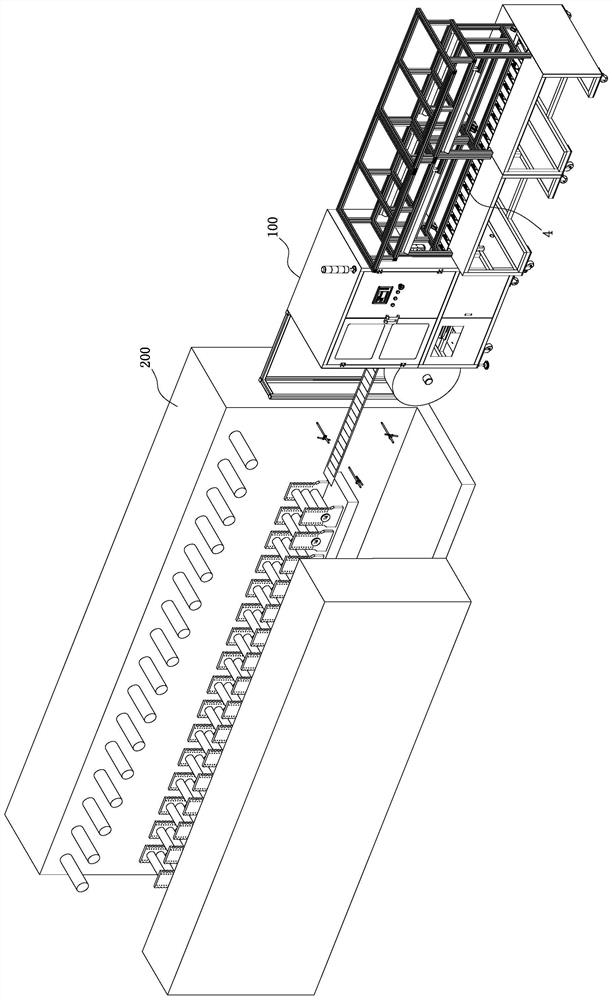
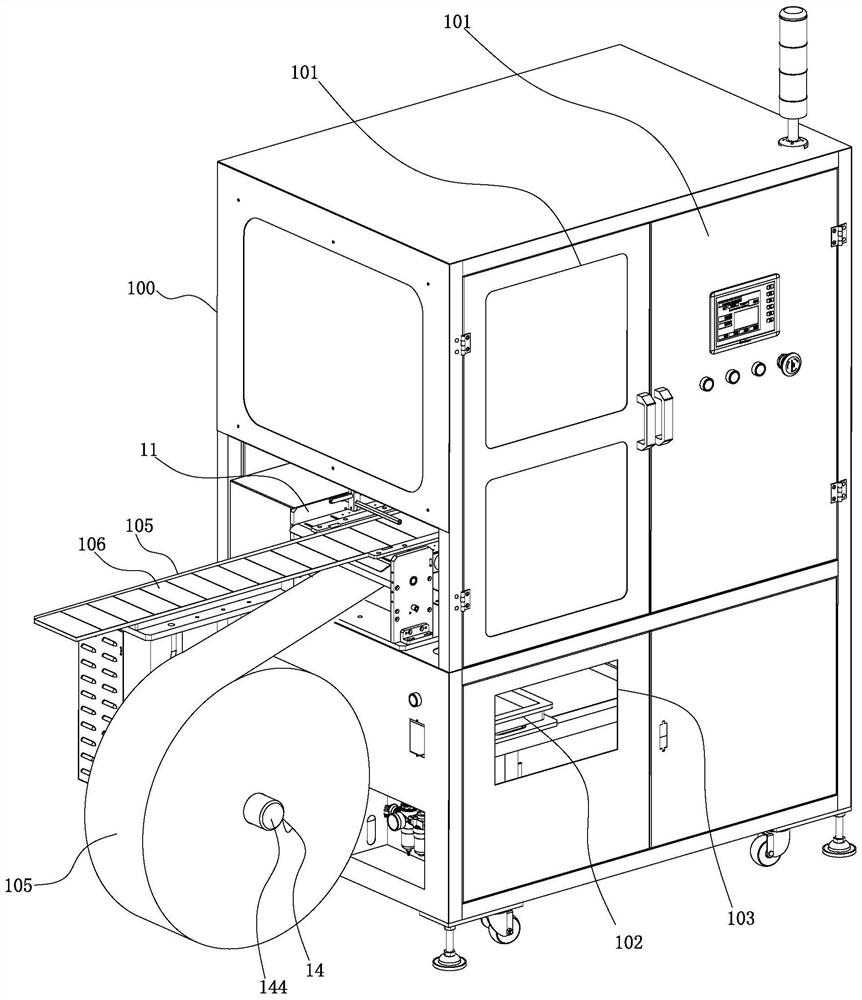
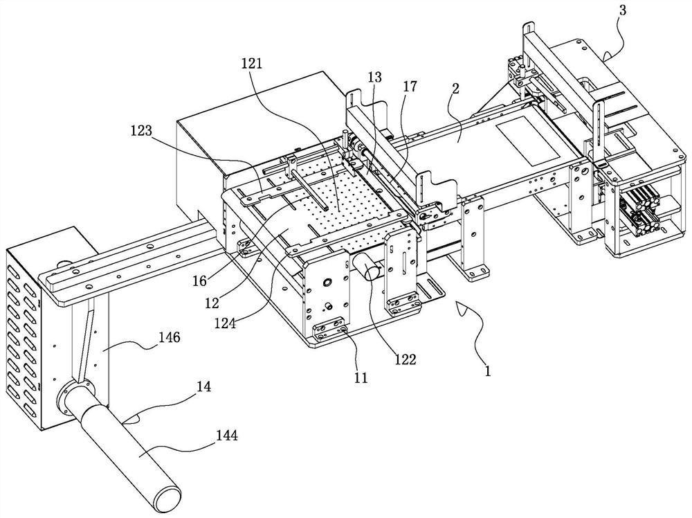
[0038] See Figure 1-16 As shown, it is a kind of peeling and sorting equipment, which includes: a casing 100; a peeling and rowing mechanism 1, which includes: a base frame 11 installed in the casing 100, a vacuum suction table 12 installed on the base frame 11, The peeling module 13 installed on the side of the vacuum adsorption table 12, the winding module 14 installed below the vacuum adsorption table 12, the base frame 11 is also provided with a defective detection module 16, the defective detection module 16 is located above the vacuum adsorption table 12; the base frame 11 is also provided with a bad row module 17, and the bad row module 17 includes a rotating shaft 171 mounted on the base frame 11, a row mounted on the lower end of the rotating shaft 171 Defective pressing plate 172 and the servomotor that is used to drive this rotating sh...


PUM


Abstract

The invention discloses a peeling and sorting device, which comprises: a casing; a mechanism for peeling and removing defects, including a base frame, a vacuum adsorption table, a peeling module, a winding module, a defect detection module and a defect removal module, and a defect removal module. The module includes a rotating shaft installed on the base frame, a bad discharge platen installed at the lower end of the rotating shaft, and a servo motor for driving the rotating shaft; a conveyor belt for good products, which is installed on the side of the peeling module; a material unloading mechanism, including the frame body, The guide plate module and the first and second material blocking components distributed in upper and lower layers and cross blocking materials, the upper end opening of the material guiding space is connected to the good product conveyor belt; the first material blocking assembly includes the first , the second linear drive module and the first and second baffles respectively installed on the first and second linear drive modules; the second stopper assembly includes the third and fourth linear drive modules and respectively installed on the first 3. The third and fourth baffles on the fourth linear drive module; the discharge conveyor belt, which is installed under the unloading mechanism.

Description

Technical field: [0001] The invention relates to the technical field of mechanical processing, in particular to a peeling and sorting device. Background technique: [0002] Circular knife machine is one of the die-cutting machines, also known as rotary machine, rotary die-cutting machine, hob machine, etc., because the knife mold used is processed from a solid metal cylinder, which is similar to the flat knife mold The circular knife machine is named after the difference. It is continuously rotated in the form of a circular knife for die-cutting. It is one of the equipment with the highest production efficiency in the die-cutting machine. [0003] In the production of the electronics industry, a large number of cut pieces of protective film are included. The sheet-shaped protective film is made by a circular knife machine. After the die-cutting is completed, the protective film (that is, the diaphragm) is placed on the film paper at equal intervals, and the film paper is wou...

Claims


Application Information

Patent Timeline
Patent Type & Authority Patents(China)
IPC IPC(8): B07C5/00B07C5/02B07C5/36B32B38/10
CPCB07C5/00B07C5/02B07C5/362B32B38/10
Inventor 刘昌跃黄民华姚小荣
Owner 深圳市高旗自动化技术有限公司
Learn More