Automatic machining equipment for aluminum rotor of ceiling fan motor

A technology for processing equipment and motor rotors, applied in the field of automated processing equipment, can solve the problems of temperature fluctuations, high work intensity of production personnel, and uneven rotor gravity, so as to reduce furnace temperature fluctuations, avoid adverse effects, and improve production yields. Effect

Pending Publication Date: 2020-06-19
NEW CENTURY ELECTRICAL MFG ZHONGSHAN
View PDF0 Cites 0 Cited by
  • Summary
  • Abstract
  • Description
  • Claims
  • Application Information

AI Technical Summary

Problems solved by technology

The die-casting production of the existing motor aluminum rotor is usually produced by a manually operated die-casting machine. Due to the rest of the staff in the middle of each shift, the mold temperature will drop, resulting in unstable mold temperature and large temperature fluctuations, resulting in a high defect rate of aluminum rotor castings.
In addition, the existing ceiling fan industry motor aluminum rotor die-casting die-casting motor aluminum rotor often has poor warping and deformation, and is not dense enough, the gravity of each part is uneven, and the instability of the mold temperature will lead to the aggravation of the above problems. It is very easy to generate electromagnetic noise, and uneven gravity can easily cause noise when the ceiling fan motor is working. Die-casting molds generally use side-to-side pouring, and the side-to-side die-casting pressure is too large. After the casting is formed, many products will have a slight ellipse. Follow-up Turning will cause more turning on one side and less turning on the other side, which will also cause uneven gravity of the rotor and generate noise
After the die-casting of the aluminum rotor of the motor, the die-casting is manually taken out from the die-casting machine. At this time, the die-casting includes two parts: the aluminum rotor of the motor and the material handle. The jig folds the material handle from the aluminum rotor of the motor. Since the material handle is located on the side of the aluminum rotor of the motor, it is easy to fix. Usually, the material handle is fixed by a clamp, and then the aluminum rotor of the motor is moved to make the two from the connection. This production method is likely to cause deformation of the aluminum rotor of the motor, which eventually leads to the generation of rotor noise
[0003] In addition, after the material handle is broken, the material handle is usually collected manually and then returned to the furnace for reuse. Because the temperature of the furnace is very high, the manual feeding work is intensive when returning to the furnace, and the weight of each feeding is different, resulting in fluctuations in the temperature of the furnace. , and after adding a large amount of handle suddenly, the temperature will drop sharply, these operations will reduce the yield rate
[0004] Due to the limitations of the existing manufacturing process, the current aluminum rotor die-casting mold for motors is usually a one-out-one structure to reduce the probability of defective products. Some companies also try to make one out of two, but the technical difficulties have not been overcome, and the defectiveness is too high. ended in failure
[0005] The existing production method of aluminum rotors for motors requires a lot of manpower, the production personnel work hard, the production efficiency is low, and the yield rate of aluminum rotors for motors is also low, which makes the quality stability of aluminum rotors for motors processed by subsequent vehicles poor.

Method used


Image

  • Automatic machining equipment for aluminum rotor of ceiling fan motor
  • Automatic machining equipment for aluminum rotor of ceiling fan motor
  • Automatic machining equipment for aluminum rotor of ceiling fan motor

Examples


Embodiment Construction

[0039] The present invention will be further described below in conjunction with accompanying drawing:

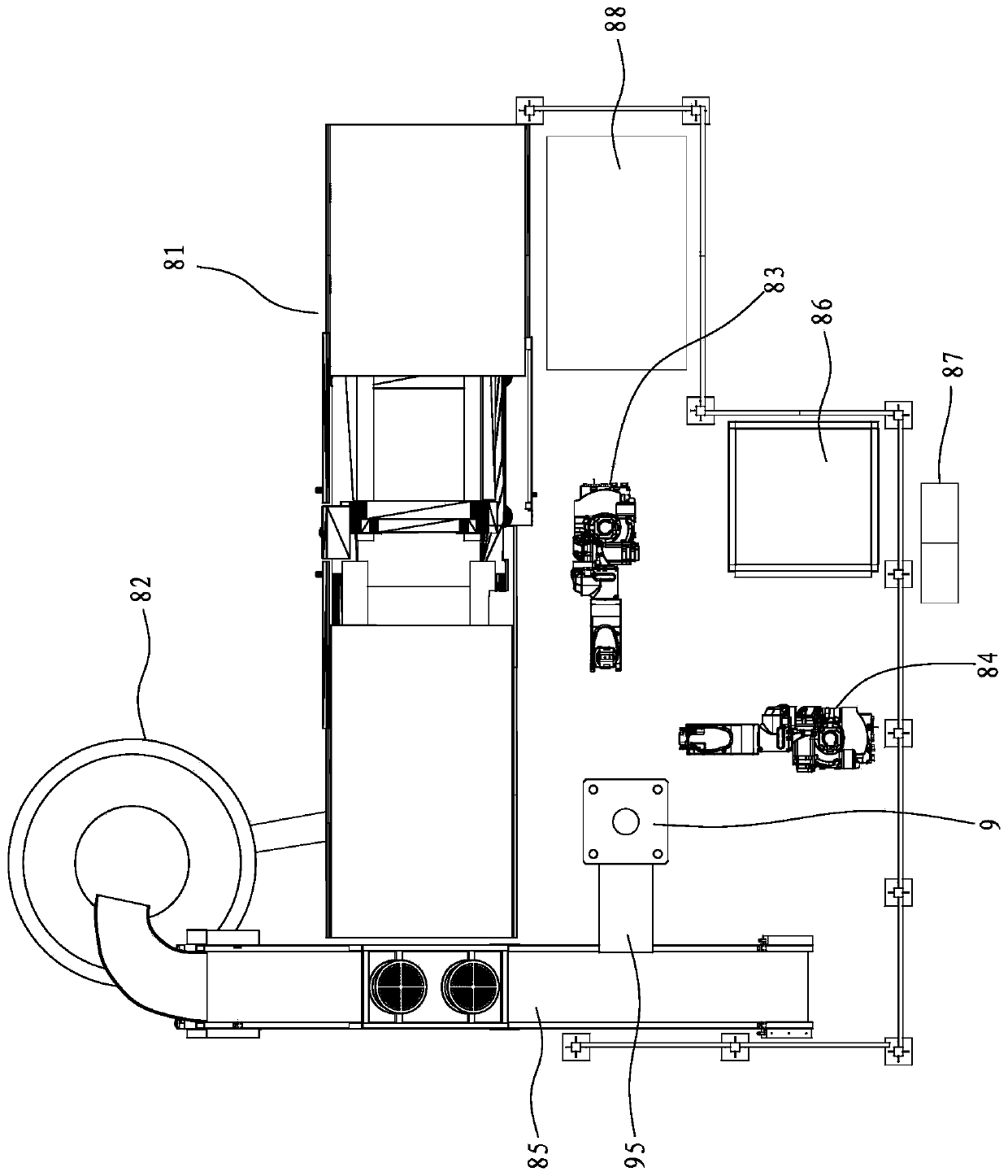
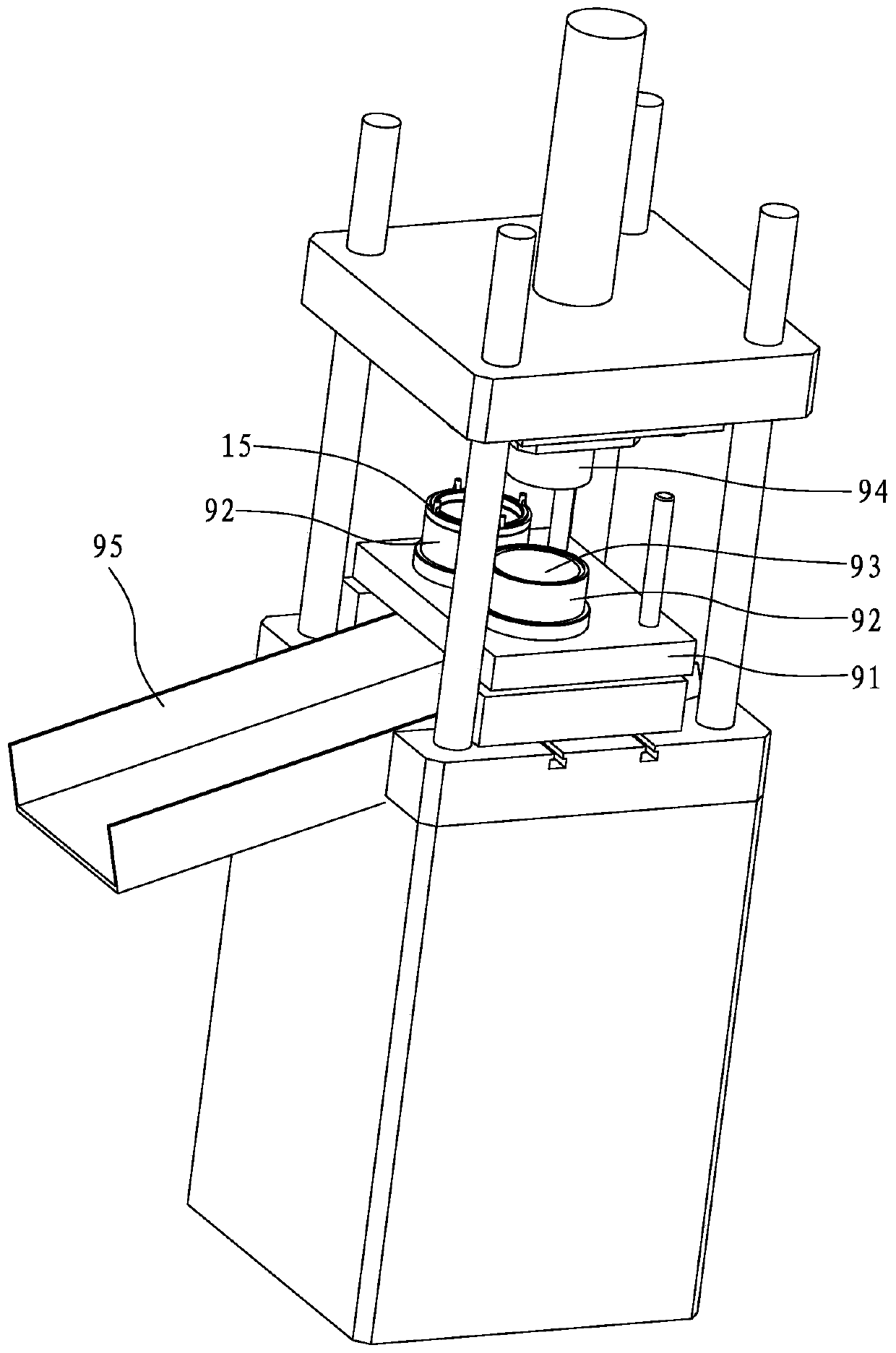
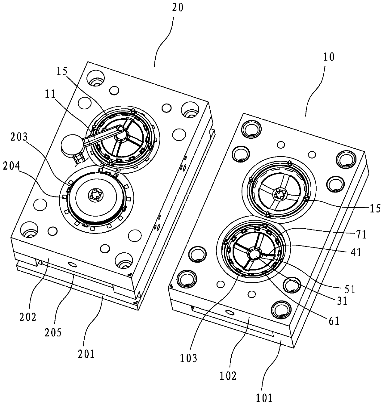
[0040] Such as Figure 1 to Figure 8 The shown automatic processing equipment for ceiling fan motor aluminum rotor includes a die-casting machine 81 and a melting furnace 82. The die-casting machine 81 is provided with a die-casting mold for die-casting the motor rotor 15. One side of the die-casting machine 81 There is a punching machine 9 capable of punching and dropping the material handle from the motor rotor 15, and there is a device between the die-casting machine 81 and the punching machine 9 for taking out the die-casting parts after mold opening in the die-casting machine 81 and putting them into the punching machine 9 A pick-up robot 83, between the punch 9 and the furnace 82 is provided with a conveyor belt 85 for catching the material handle punched by the punch 9 and transporting the material handle to the furnace 82, and one side of the punch 9 is provided wit...


PUM


Abstract

The invention discloses automatic machining equipment for an aluminum rotor of a ceiling fan motor. The automatic machining equipment comprises a die-casting machine and a smelting furnace, wherein adie-casting die is arranged in the die-casting machine, a punching machine capable of punching a material handle to enable the material handle to fall off from the motor rotor is arranged on one sideof the die-casting machine, a workpiece taking robot used for taking out die castings in the die-casting machine and placing the die castings into the punching machine is arranged between the die-casting machine and the punching machine, a conveying belt used for receiving the material handles punched by the punching machine and conveying the material handles into the smelting furnace is arrangedbetween the punching machine and the smelting furnace, a material collecting frame is arranged on one side of the punching machine, a stacking robot is arranged between the punching machine and the material collecting frame, a control system controls the workpiece taking robot, the stacking robot, the conveying belt and the punching machine to work, automatic production of die-cast forming, takingdown the die castings from the die-casting die, moving the die castings to the punching machine, punching the material handles, orderly stacking the punched motor rotors and returning the material handles punched each time to the smelting furnace is achieved, the production efficiency is high, the furnace temperature fluctuation is small, and the production yield is high.

Description

【Technical field】 [0001] The invention relates to an automatic processing equipment for an aluminum rotor of a ceiling fan motor. 【Background technique】 [0002] The aluminum rotor of the ceiling fan motor is usually formed by die-casting by a die-casting machine, and then processed after being removed from the nozzle. Existing die-casting production of aluminum rotors for electric motors is usually produced by manually operated die-casting machines. Due to rest in the middle of each shift, the mold temperature will drop, resulting in unstable mold temperature and large temperature fluctuations, resulting in a high defect rate of aluminum rotor castings. In addition, the existing ceiling fan industry motor aluminum rotor die-casting die-casting motor aluminum rotor often has poor warping and deformation, and is not dense enough, the gravity of each part is uneven, and the instability of the mold temperature will lead to the aggravation of the above problems. It is very easy...

Claims


Application Information

Patent Timeline
Patent Type & Authority Applications(China)
IPC IPC(8): B22D17/20B22D17/22B22D17/32B22D31/00B22D47/00
CPCB22D17/2076B22D17/2084B22D17/22B22D17/2272B22D17/32B22D47/00
Inventor 卢齐荣
Owner NEW CENTURY ELECTRICAL MFG ZHONGSHAN
Why Eureka
Try Eureka