
Metal powder selective laser melting defect suppression device

A technology of laser selective melting and metal powder, which is applied in the direction of additive manufacturing, process efficiency improvement, additive processing, etc., can solve the problems of reducing the precision and mechanical properties of formed parts, uneven distribution of temperature field, and void defects of formed parts, etc. Achieve the effects of reducing upgrade costs, suppressing spatter, and suppressing defects

Pending Publication Date: 2020-06-19
HUAZHONG UNIV OF SCI & TECH
View PDF7 Cites 4 Cited by
  • Summary
  • Abstract
  • Description
  • Claims
  • Application Information

AI Technical Summary

Problems solved by technology

There are two main reasons. The first reason is the Marangoni effect, that is, in the process of SLM forming parts, the temperature gradient between the center of the molten pool and the edge area causes the liquid metal to flow from the center of the molten pool to the edge, resulting in the flow of liquid metal and causing temperature The field distribution is uneven, resulting in stress concentration and cracks; the second reason is that during the SLM forming process, the movement of metal particles in the molten pool causes the liquid metal to form splashes, and the splashed liquid drops on the solidification surface to form small metal particles, affecting The powder coating and fusion of the next layer lead to void defects inside the formed part, which will seriously reduce the accuracy and mechanical properties of the formed part
At present, the Marangoni effect for the first reason can be overcome by heating the molten pool to make the temperature distribution inside the molten pool uniform, but there is no better method for the SLM forming defects caused by the second reason

Method used


Image

  • Metal powder selective laser melting defect suppression device

Examples


Embodiment Construction

[0026] In order to make the object, technical solution and advantages of the present invention clearer, the present invention will be further described in detail below in conjunction with the accompanying drawings and embodiments. It should be understood that the specific embodiments described here are only used to explain the present invention, not to limit the present invention. In addition, the technical features involved in the various embodiments of the present invention described below can be combined with each other as long as they do not constitute a conflict with each other.

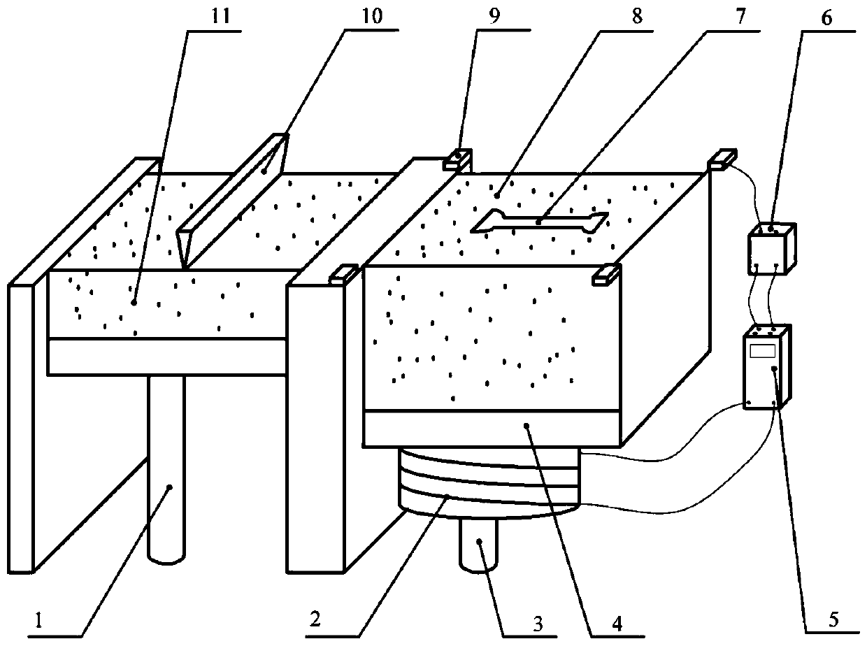
[0027] Such as figure 1 Shown is a schematic structural view of the embodiment of the application installed on the SLM forming equipment;

[0028] SLM forming equipment includes 1 powder feeding cylinder piston, 4 working platforms, 7 forming parts, 8 powder layers, 10 powder spreading scrapers and 11 powder feeding cylinders;

[0029] The embodiment of the present application includes an exci...


PUM

PropertyMeasurementUnit
Diameteraaaaaaaaaa
Total resistanceaaaaaaaaaa

Abstract

The invention discloses a metal powder selective laser melting defect suppression device and belongs to the technical field of metal additive manufacturing. According to the metal powder selective laser melting defect suppression device, according to the Lenz's law and the Hall effect principle, liquid-state conductive metal will produce electromagnetic force in the magnetic field in the flowing process, the force has great influences on the flowing behavior of a molten pool, and therefore the metallurgical defects of formed parts are inhibited. The metal powder selective laser melting defectsuppression device comprises an excitation device, a magnetic field measuring device and a magnetic field control device. The excitation device comprises a coil and an iron core which is placed insidethe coil; the magnetic field measuring device is composed of four magnetic field sensors which are distributed at the four corners of a work platform, and used for measuring the magnetic field strength of a forming area; and the magnetic field control device adjusts the current in the coil to control the magnetic field strength and direction. The device has the advantages of being simple in structure, convenient to adjust, low in cost, and being capable of easily assembled to an existing metal powder selective laser melting device and the like, and can effectively suppress the metallurgical defects of the formed parts.

Description

technical field [0001] The invention belongs to the technical field of metal additive manufacturing, and more specifically relates to a metal powder laser selective melting defect suppression device. Background technique [0002] Additive manufacturing, also known as rapid prototyping or 3D printing, is a technology based on digital model files, using materials in the form of liquid, powder, wire, etc., to manufacture physical parts by stacking and accumulating layer by layer. Common additive manufacturing technologies include fused deposition modeling (FDM), stereolithography (SLA), and selective laser melting (SLM). Among them, SLM has become the metal additive manufacturing technology with the greatest practical significance due to its advantages such as wide range of forming materials, excellent mechanical properties of formed parts (better than forgings of the same material), high density, and high precision of formed parts, and has been widely used at home and abroad. ...

Claims


Application Information

Patent Timeline
IPC IPC(8): B22F3/105B33Y30/00
CPCB33Y30/00B22F10/00B22F10/38B22F12/30B22F12/90B22F10/28Y02P10/25
Inventor 曹龙超周奇吴金红胡杰翔李京昌程吉盛闽华彭玉童
Owner HUAZHONG UNIV OF SCI & TECH
Learn More