Supercharge Your Innovation With Domain-Expert AI Agents!

Power battery thermal management system based on combination of two-stage heat pipe and vehicle body

A heat management system and power battery technology, applied in the direction of secondary batteries, circuits, electrical components, etc., to achieve the effect of easy maintenance, shortened heat exchange distance, simple and compact

Active Publication Date: 2020-06-19
CHINA UNIV OF MINING & TECH +1
View PDF5 Cites 1 Cited by
  • Summary
  • Abstract
  • Description
  • Claims
  • Application Information

AI Technical Summary

Problems solved by technology

Although the heat pipe, as an efficient heat transport medium, can quickly transport the heat absorbed from the battery to the outside of the battery system, the heat dissipation capacity of the condensing end is the bottleneck factor restricting the performance of the heat pipe cooling system.

Method used


Image

  • Power battery thermal management system based on combination of two-stage heat pipe and vehicle body
  • Power battery thermal management system based on combination of two-stage heat pipe and vehicle body
  • Power battery thermal management system based on combination of two-stage heat pipe and vehicle body

Examples


Embodiment 1

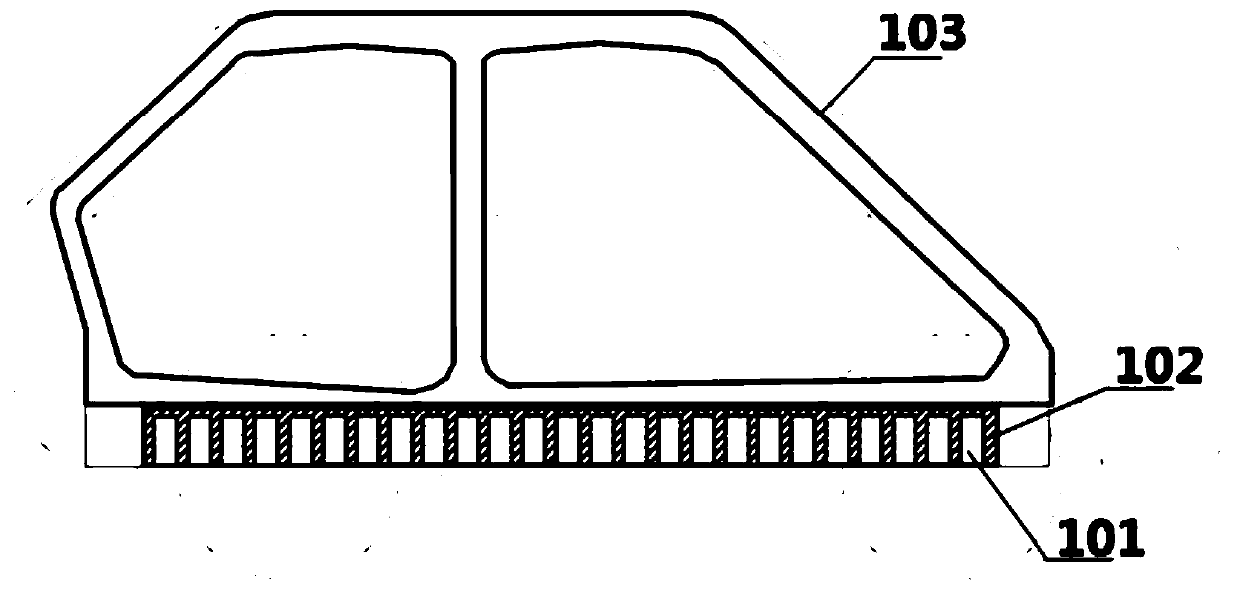
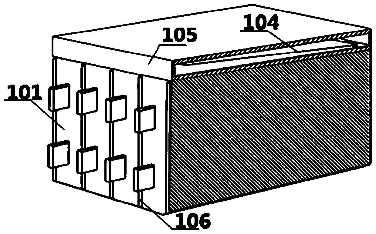
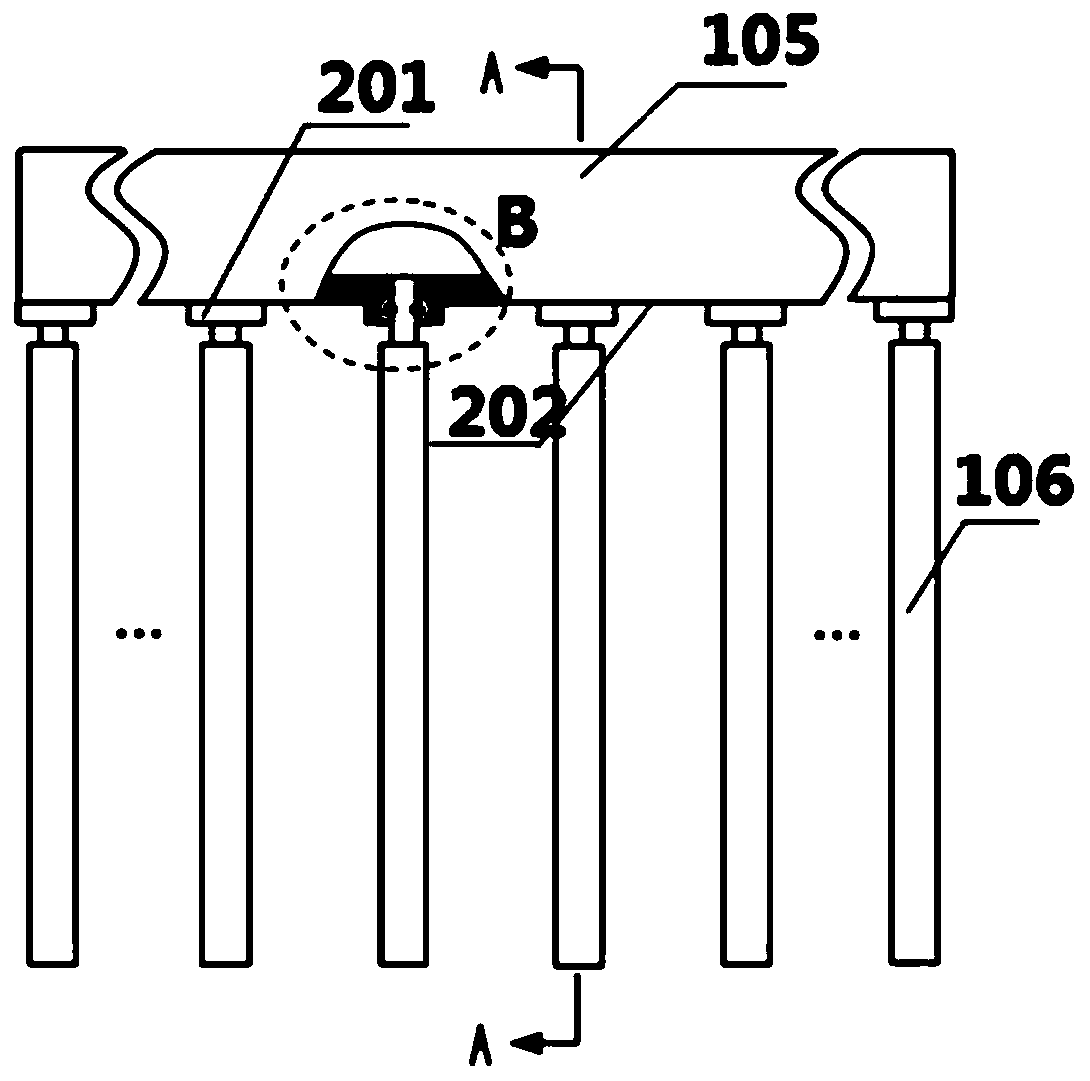
[0026] As shown in the figure, a power battery thermal management system based on the combination of two-stage heat pipes and the body includes several power battery cells 101, a three-dimensional ultra-thin heat pipe group 102 and a body heat pipe 103; the three-dimensional ultra-thin heat pipe group 102 is arranged on the body The bottom is composed of several ultra-thin evaporation plates 106 and a condenser 105; in order to enhance the detachability of the three-dimensional ultra-thin heat pipe group 102, the bottom surface 202 of the condenser 105 contains a tapered interface 201; the flexible joint of the ultra-thin evaporation plate 106 307 is connected to the tapered interface 201 through a sealing ring 305 and a self-carding collar 306; the condenser 105 contains a gas-liquid splitter plate 104, and the gas-liquid splitter plate 104 separates the three-dimensional ultra-thin heat pipe group 102 into several parallel Complete circuit; the two surfaces of the power batte...

Embodiment 2

[0031] In this embodiment, the evaporation chamber inside the ultra-thin evaporation plate 106 contains a micro-channel 501 structure with a hydraulic diameter stepwise change, and the diameter of the micro-channel 501 gradually decreases in the direction away from the return channel 301, and other implementation methods are the same as in the first embodiment. .

Embodiment 3

[0033] In this embodiment, the evaporation cavity inside the ultra-thin evaporation plate 106 contains a gradient porous structure 601 , and the average diameter of the pores gradually decreases in the direction away from the return channel 301 , and other implementation methods are the same as in the first embodiment.


PUM


Abstract

The invention discloses a power battery thermal management system based on combination of a two-stage heat pipe and a vehicle body. The system comprises a three-dimensional ultrathin heat pipe group and a vehicle body heat pipe. The three-dimensional ultrathin heat pipe set is composed of a plurality of ultrathin evaporation plates and a condenser. A gas-liquid splitter plate is arranged in the condenser. The bottom surface comprises a reducing interface. The ultrathin evaporation plate is connected with the tapered interface through a sealing ring and a self-clamping lantern ring. The singlepower battery is tightly attached to the two ultrathin evaporation plates of the three-dimensional ultrathin heat pipe set, the upper surface of the condenser is tightly attached to a bottom heat absorption cavity of the automobile body heat pipe through a high-heat-conduction material, and heat generated by the power battery can be rapidly transmitted to an automobile roof through two-stage gas-liquid phase change heat transfer to dissipate heat to the environment. The power battery heat management system and the automobile body structure are ingeniously integrated, the heat dissipation areais increased, heat dissipation can be conducted through airflow in the movement process of an automobile, the structure is simple, the battery pack structure is compact, the temperature control performance is good, and the wide market prospect is achieved.

Description

technical field [0001] The invention belongs to the field of power battery thermal management, and in particular relates to a power battery thermal management system based on the combination of a two-stage heat pipe and a vehicle body. Background technique [0002] Energy shortage and environmental pollution have become difficult problems facing the development of the world today, and the electric transformation and development of the automobile industry has great potential in the field of energy conservation and emission reduction. New energy electric vehicles occupy an important position in new energy vehicles because of their green and environmental protection advantages. The power of new energy electric vehicles comes from a battery pack composed of multiple single power batteries. During the process of charging and discharging, the power battery generates heat due to incomplete energy conversion. If the heat dissipation is not timely, it will cause the local temperatur...

Claims


Application Information

Patent Timeline
IPC IPC(8): H01M10/613H01M10/625H01M10/6552H01M10/6569
CPCH01M10/613H01M10/625H01M10/6552H01M10/6569Y02E60/10
Inventor 赵佳腾姜威饶中浩周寿斌姜庆海吴战宇
Owner CHINA UNIV OF MINING & TECH
Features
  • R&D
  • Intellectual Property
  • Life Sciences
  • Materials
  • Tech Scout
  • Unparalleled Data Quality
  • Higher Quality Content
  • 60% Fewer Hallucinations
Learn More