Power driving system and vehicle
A power drive and power coupling technology, applied in hybrid vehicles, motor vehicles, power units, etc., can solve the problems of long transmission chain length, low transmission efficiency, power interruption, etc., to achieve overall compactness, improve operating efficiency, gear shift Small drop effect
- Summary
- Abstract
- Description
- Claims
- Application Information
AI Technical Summary
Problems solved by technology
Method used
Image
Examples
Embodiment 1
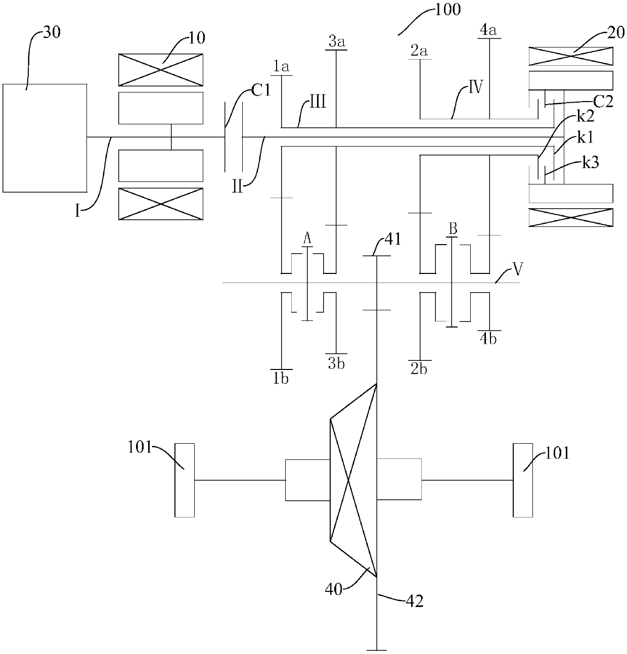
[0083] Embodiment one, such as figure 1 As shown, the first shaft I is connected to the crankshaft of the engine 30, the rotor of the first motor generator 10 is fixedly connected to the first shaft I, and the first motor generator 10 is connected to the crankshaft of the engine 30 through the first shaft I. In addition, in A first clutch C1 is provided between the first shaft I and the second shaft II. The first clutch C1 connects or disconnects the power between the first shaft I and the second shaft II. The rotor of the second motor generator 20 and the second shaft The two axes II are fixedly connected.
[0084] Such as figure 1 As shown, the second clutch C2 includes a third part k3, a first part k1, and a second part k2 that cooperate with each other. The third part k3 is fixed to the rotor of the second motor-generator 20. In addition, the third shaft III passes through the sleeve shaft. Arranged concentrically with the second shaft II, the fourth shaft IV is also con...
Embodiment 2
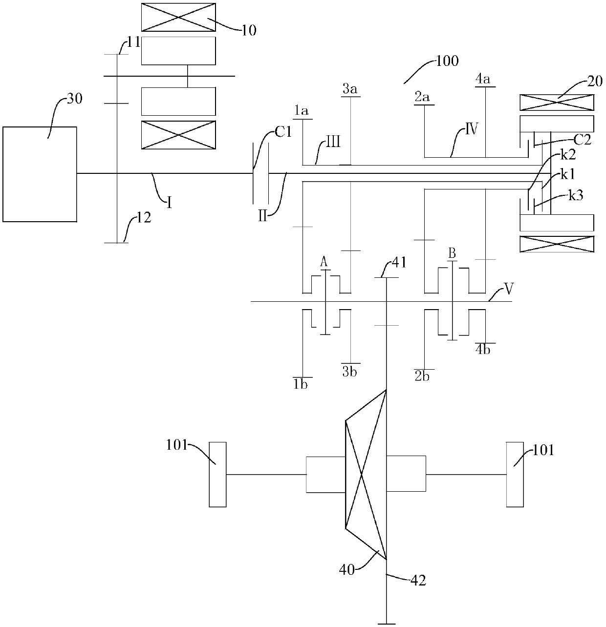
[0086] Embodiment two, such as figure 2 As shown, the first shaft I is connected to the crankshaft of the engine 30, the motor shaft of the first motor generator 10 is provided with a motor side gear 11, the first shaft I is fixedly provided with a first shaft side gear 12, and the motor side gear 11 is connected to the first shaft side gear 11. The first shaft side gear 12 meshes, and the first motor generator 10 is connected to the first shaft I through the motor side gear 11 and the first shaft side gear 12. In addition, a first Clutch C1. The first clutch C1 connects or disconnects the power between the first shaft I and the second shaft II, and the rotor of the second motor generator 20 is fixedly connected to the second shaft II.
[0087] Such as figure 2 As shown, the second clutch C2 includes a third part k3, a first part k1 and a second part k2 that cooperate with each other. The third part k3 is fixed to the rotor of the second motor generator 20, and the rotor is...
Embodiment 3
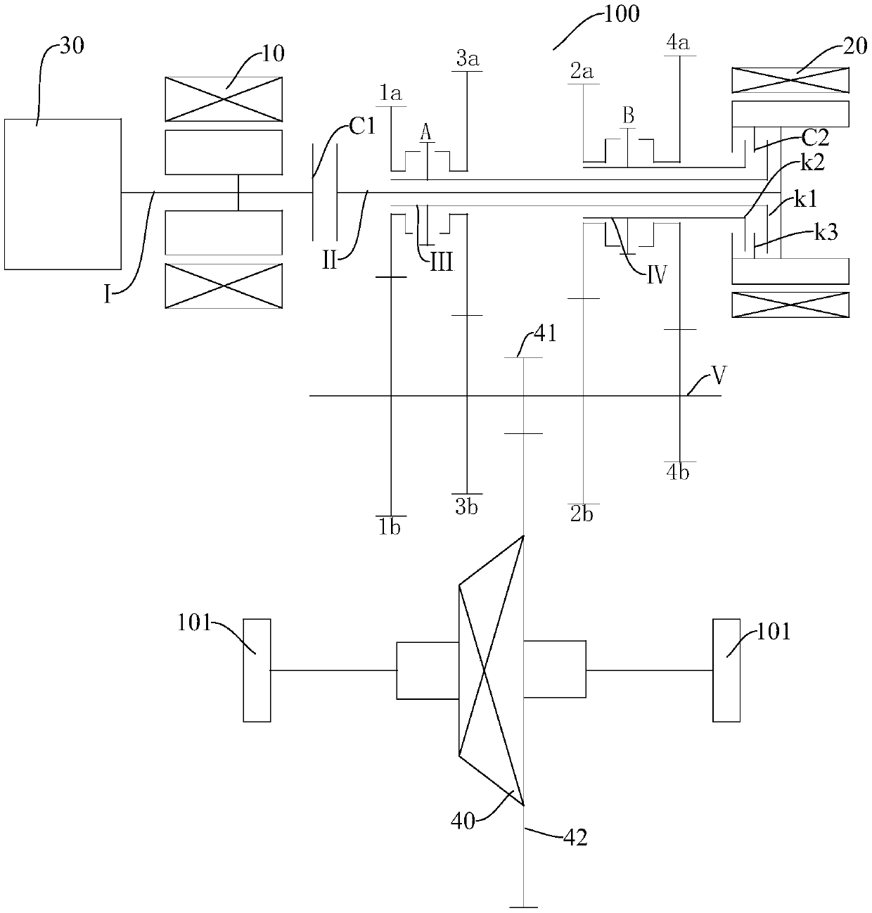
[0089] Embodiment three, such as image 3 As shown, the first shaft I is connected to the crankshaft of the engine 30, the rotor of the first motor generator 10 is fixedly connected to the first shaft I, and the first motor generator 10 is connected to the crankshaft of the engine 30 through the first shaft I. In addition, in A first clutch C1 is provided between the first shaft I and the second shaft II. The first clutch C1 connects or disconnects the power between the first shaft I and the second shaft II. The rotor of the second motor generator 20 and the second shaft The two axes II are fixedly connected.
[0090] Such as image 3 As shown, the second clutch C2 includes a third part k3, a first part k1 and a second part k2 that cooperate with each other. The third part k3 is fixed to the rotor of the second motor-generator 20 and connected to the second clutch C2 casing. In addition, the third shaft III is arranged concentrically with the second shaft II through the slee...
PUM
 Abstract
Description
Claims
Application Information
 - R&D
- Intellectual Property
- Life Sciences
- Materials
- Tech Scout
- Unparalleled Data Quality
- Higher Quality Content
- 60% Fewer Hallucinations
Browse by: Latest US Patents, China's latest patents, Technical Efficacy Thesaurus, Application Domain, Technology Topic, Popular Technical Reports.
© 2025 PatSnap. All rights reserved.Legal|Privacy policy|Modern Slavery Act Transparency Statement|Sitemap|About US| Contact US: help@patsnap.com


