Carbon-polymer structure with photothermal effect and thermal conductivity and its preparation method and application
A technology of thermal conductivity and photothermal effect, which is applied in the field of carbon-polymer structure and its preparation, can solve the problems of limited application and achieve the effect of simple preparation method, ingenious design and good application prospects
- Summary
- Abstract
- Description
- Claims
- Application Information
AI Technical Summary
Problems solved by technology
Method used
Image
Examples
Embodiment 1
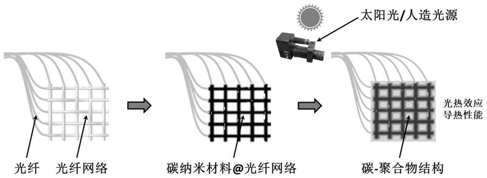
[0042] A method for preparing a carbon-polymer structure with photothermal effect and thermal conductivity, comprising the following steps:
[0043] 1) Prepare multiple optical fibers: strip off the optical fiber coating layer at one end of a bundle of optical fibers, use the optical fiber bundle without the optical fiber coating layer as the a-segment fiber bundle, and use the stripped optical fiber segment as the b-segment optical fiber;
[0044] Weaving a plurality of b-segment optical fibers together to form a heat dissipation structure (in the heat dissipation structure, the optical fibers are not coated with an optical fiber coating layer), the heat dissipation structure is a square grid structure, and the side length of the square mesh in the square grid structure is 2mm, and then Repeat the coating thickness control method for the heat dissipation structure once, so that a carbon nanomaterial coating with a thickness of 1 μm (ie, carbon nanomaterial@fiber network) is f...
Embodiment 2
[0048] A preparation method of a carbon-polymer structure with photothermal effect and thermal conductivity, comprising the following steps:
[0049] 1) Prepare multiple optical fibers: strip off the optical fiber coating layer at one end of a bundle of optical fibers, use the optical fiber bundle without the optical fiber coating layer as the a-segment fiber bundle, and use the stripped optical fiber segment as the b-segment optical fiber;
[0050] A plurality of b-segment optical fibers are braided together to form a heat dissipation structure (in the heat dissipation structure, the optical fibers are not coated with an optical fiber coating layer). The distance between adjacent optical fibers is 2 mm, and the coating thickness adjustment method is repeated for the heat dissipation structure 5 times, so that a carbon nanomaterial coating with a thickness of 20 μm is formed on the heat dissipation structure, and an optical fiber network connected to the a-section fiber bundle...
Embodiment 3
[0054] A preparation method of a carbon-polymer structure with photothermal effect and thermal conductivity, comprising the following steps:
[0055] 1) Prepare multiple optical fibers: strip off the optical fiber coating layer at one end of a bundle of optical fibers, use the optical fiber bundle without the optical fiber coating layer as the a-segment fiber bundle, and use the stripped optical fiber segment as the b-segment optical fiber;
[0056] A plurality of b-segment optical fibers are braided together to form a heat dissipation structure (in the heat dissipation structure, the optical fibers are not coated with an optical fiber coating layer), and the heat dissipation structure is a three-dimensional structure. A cylindrical structure and a b-segment optical fiber is set at the center of the cylindrical structure (the b-segment fibers in the cylindrical structure are parallel to each other), wherein, on each of the multiple concentric circles, the distance between any ...
PUM
| Property | Measurement | Unit |
|---|---|---|
| thickness | aaaaa | aaaaa |
| length | aaaaa | aaaaa |
| thickness | aaaaa | aaaaa |
Abstract
Description
Claims
Application Information
 - R&D
- Intellectual Property
- Life Sciences
- Materials
- Tech Scout
- Unparalleled Data Quality
- Higher Quality Content
- 60% Fewer Hallucinations
Browse by: Latest US Patents, China's latest patents, Technical Efficacy Thesaurus, Application Domain, Technology Topic, Popular Technical Reports.
© 2025 PatSnap. All rights reserved.Legal|Privacy policy|Modern Slavery Act Transparency Statement|Sitemap|About US| Contact US: help@patsnap.com


