

Pipeline passive zero energy consumption freeze-proofing device based on PCM
An antifreeze device and zero energy consumption technology, which is applied in pipeline anticorrosion/rust protection, pipeline protection, pipeline heating/cooling, etc., to achieve the effects of enhancing stability, strengthening heat transfer, and prolonging antifreeze time
- Summary
- Abstract
- Description
- Claims
- Application Information
AI Technical Summary
Problems solved by technology
Method used
Image

Examples
Embodiment Construction
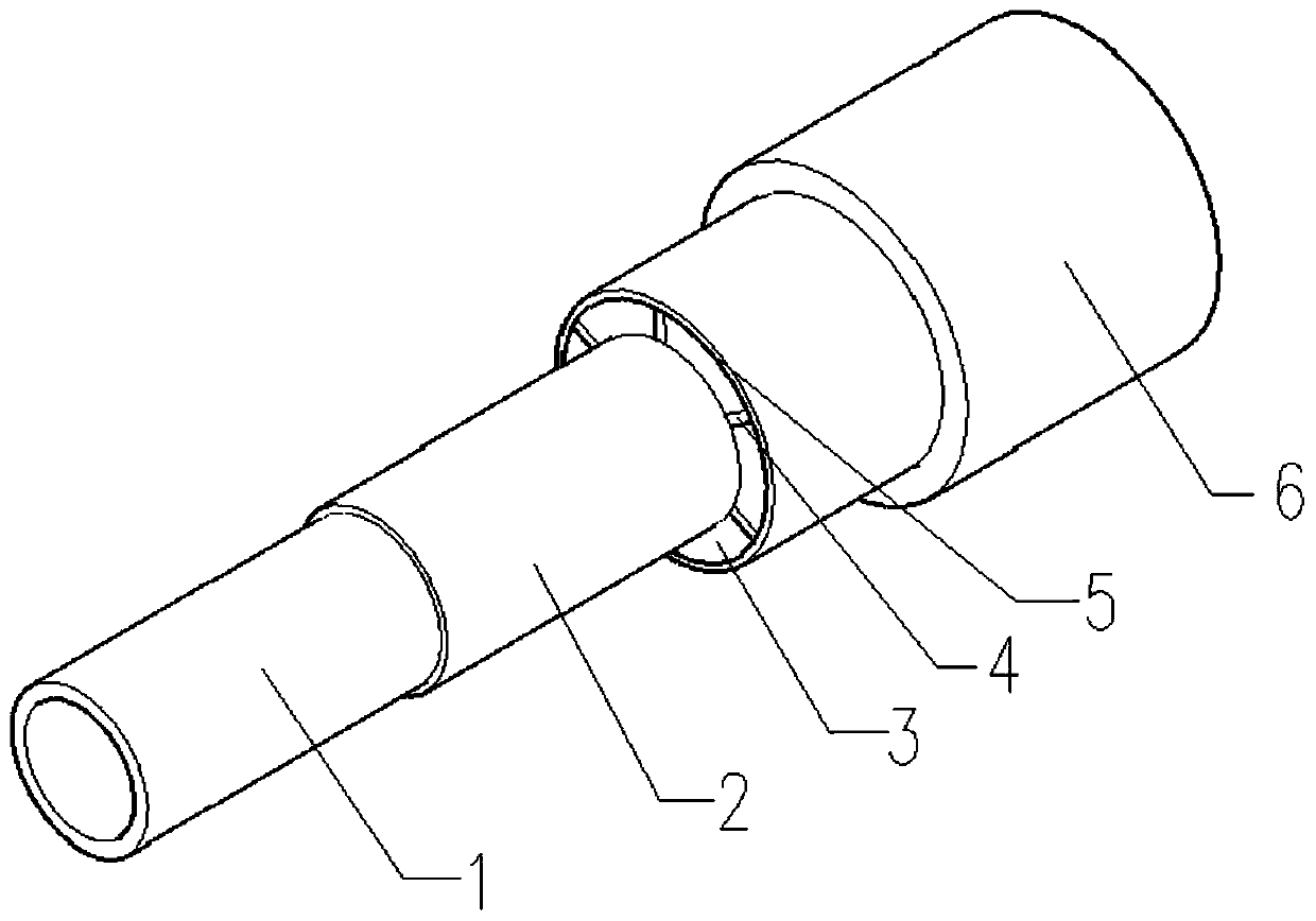
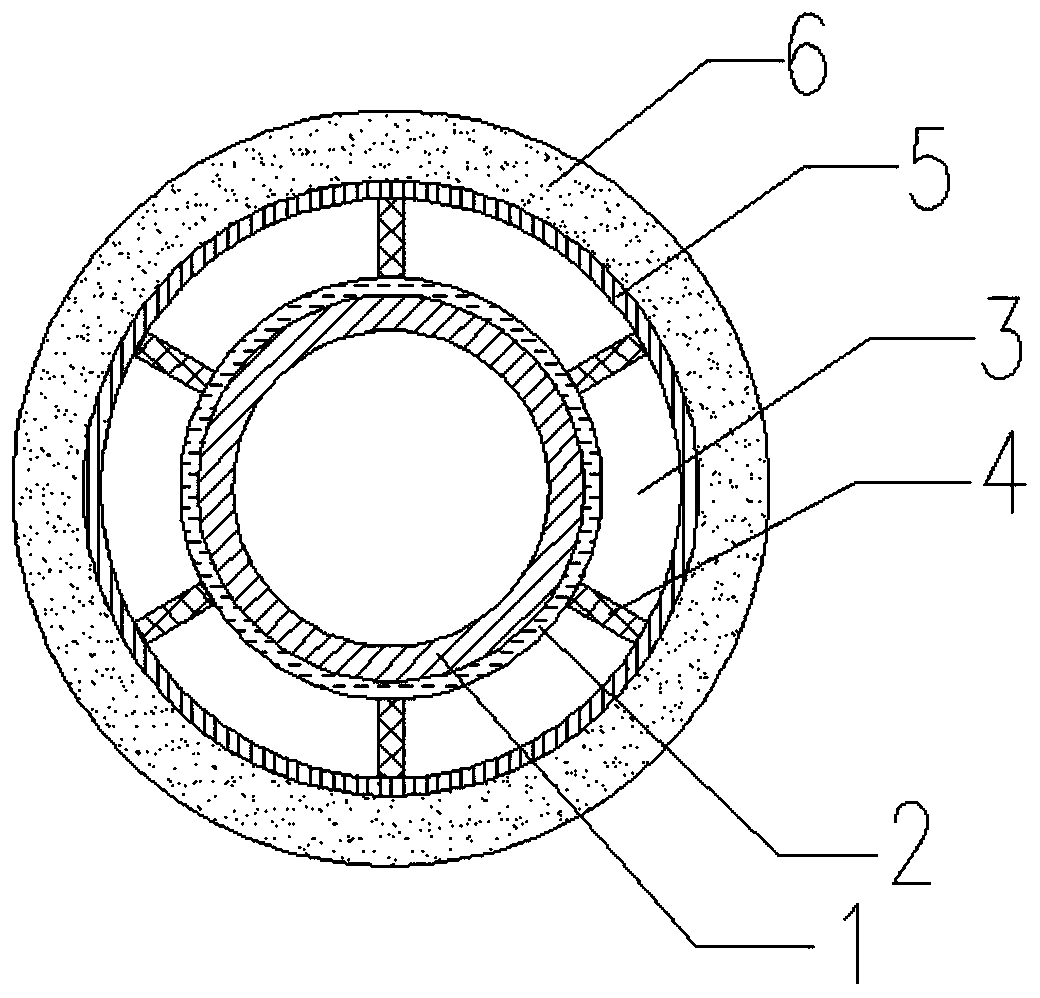
[0033] Concrete structure of the present invention sees figure 1 , 2 , which is a composite layered pipe structure including working pipe, anti-corrosion layer, PCM layer, embedded bracket, casing and heat insulation layer.
[0034] The PCM mentioned in the present invention, that is, phase change material (phase change material), refers to a class of materials that can absorb or release a large amount of energy (ie phase change enthalpy) when a substance undergoes a phase change. Phase change materials use latent heat to store and release heat. They have the characteristics of high heat storage density, compact structure of heat storage devices, basically unchanged temperature during the phase change process, and easy management. They have great potential for engineering applications.
[0035] The working tube 1 is located on the innermost side and is used to transmit the working medium; the PCM layer 3 is located in the cavity structure between the anti-corrosion layer 2 an...
PUM
 Abstract
Description
Claims
Application Information