Fire emergency lamp
A technology for fire emergency and light boxes, which is applied to lampshades, gas-proof/waterproof devices, lighting and heating equipment, etc. It can solve problems such as failures and corrosion of charging lines, and achieve improved sealing, enhanced illumination, and improved guidance effects. Effect
- Summary
- Abstract
- Description
- Claims
- Application Information
AI Technical Summary
Problems solved by technology
Method used
Image

Examples
Embodiment 1
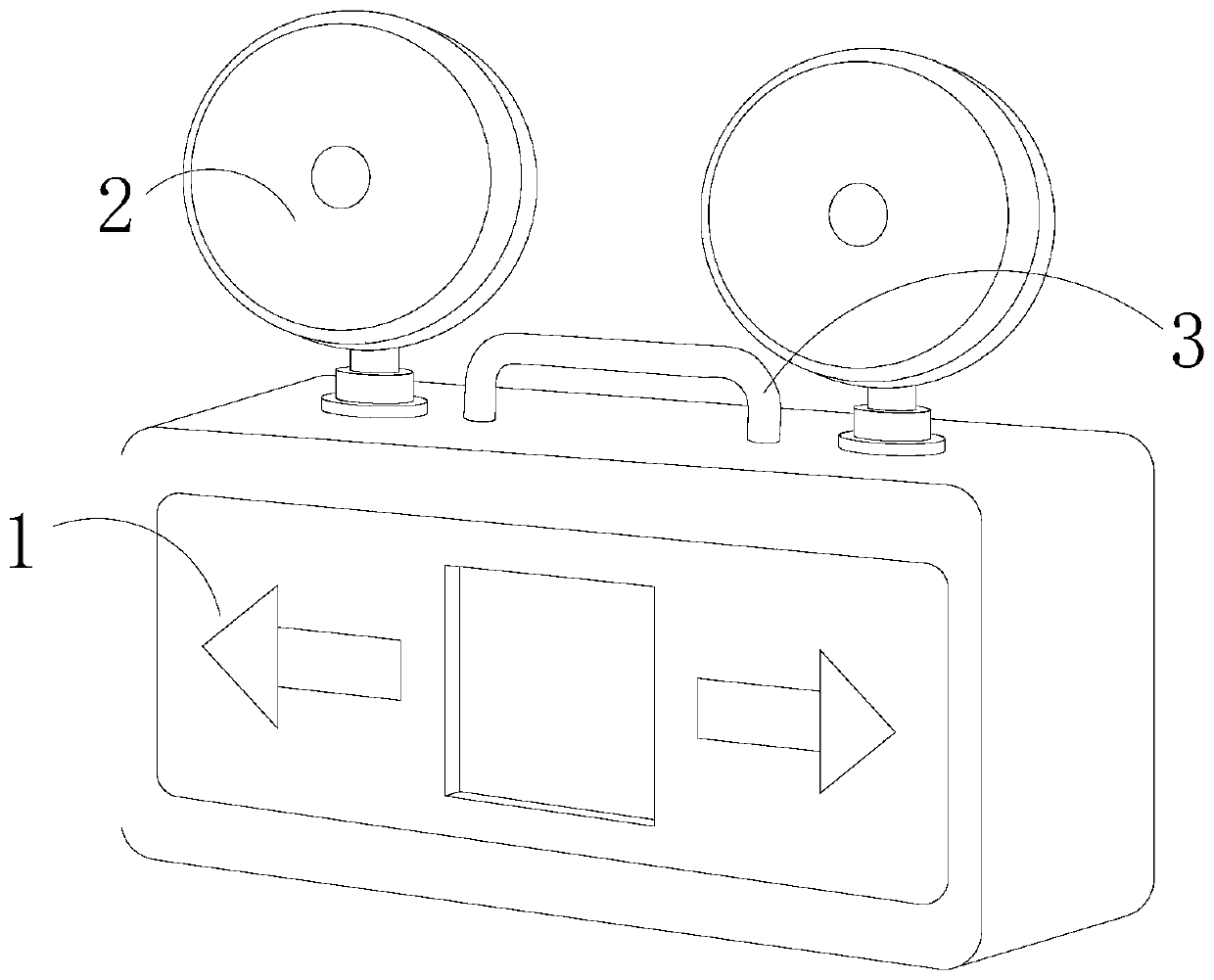
[0029] see Figure 1-Figure 6 :
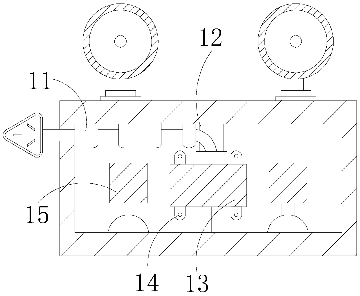
[0030] A fire emergency light, its structure includes a light box 1, a lighting lamp 2, and a handle 3, the lighting lamp 2 is connected to the upper surface of the light box 1 through movable engagement, and the handle 3 is connected to the top of the light box 1 by welding. The light box 1 includes a line pipe 11, a positioning frame 12, a battery 13, a fixing plate 14, and an indicator light 15. The line pipe 11 and the positioning frame 12 are respectively connected to the upper inner wall of the light box 1 by welding, and the battery 13 is installed on the Inside the light box 1, the fixed plate 14 is embedded in the upper and lower sides of the battery 13, and the indicator light 15 is installed on both sides of the battery 13. The fixed plate 14 has four pieces and is provided with screw grooves, which is beneficial to fixing the battery 13.
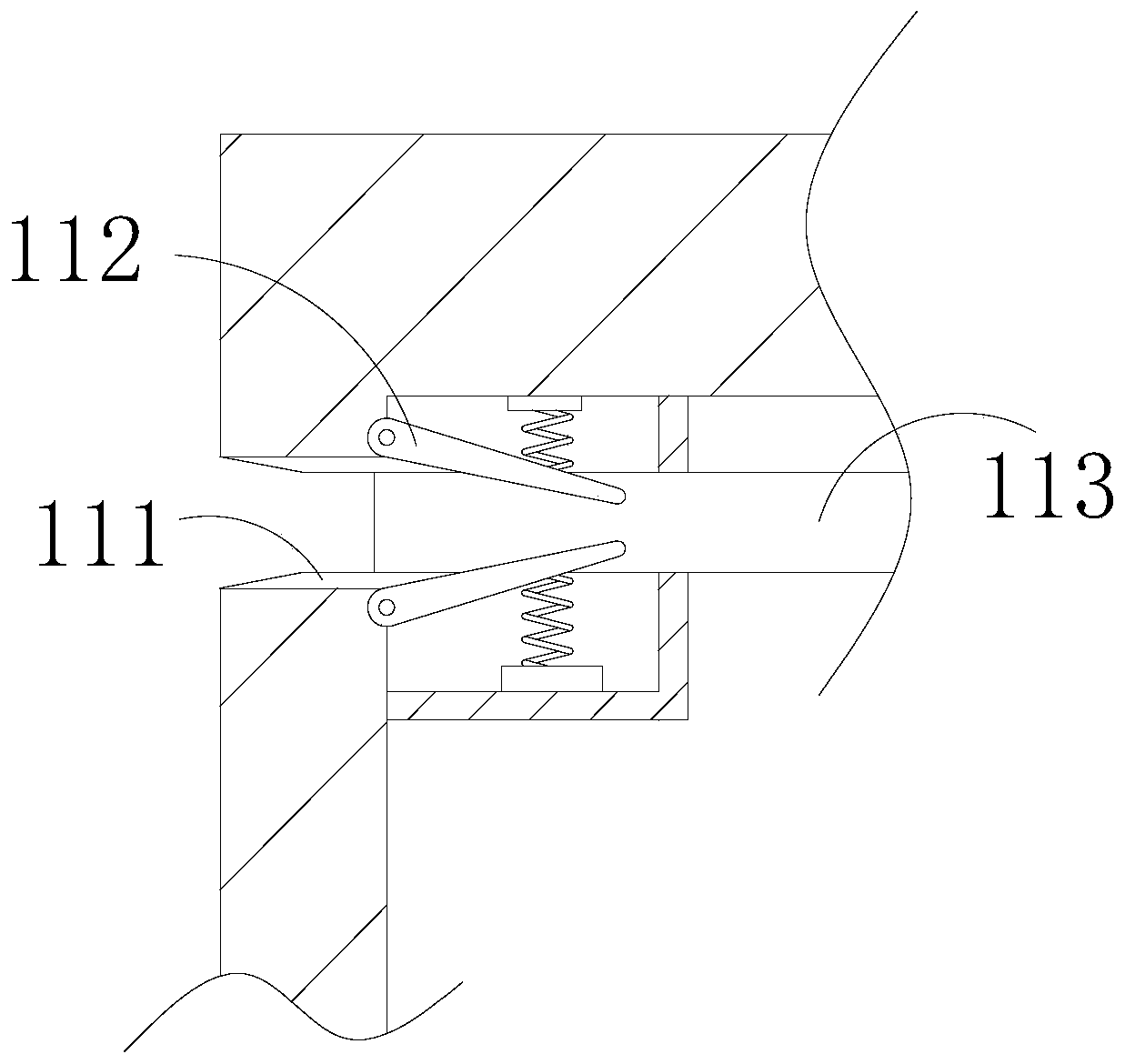
[0031] In the figure, the line pipe 11 includes a sealing ring 111, a rubber plate 112, and ...
Embodiment 2
[0037] see Figure 7-Figure 8 :
[0038]In the figure, the indicator light 15 includes a support rod b1, a rotating bead b2, a rotating shaft b3, and a lampshade b4. The support rod b1 is connected to the bottom of the indicator light 15 by welding, and the rotating bead b2 is embedded in the end of the support rod b1. The rotating shaft b3 is fitted under the rotating bead b2, the lampshade b4 is installed on the surface of the indicator light 15, the rotating shaft b3 is electrically connected to the battery 13, and the rotating bead b2 is engaged with the rotating shaft b3, which is beneficial for the rotating shaft b3 to drive the lampshade b4 Rotate, thereby change the illumination direction of indicator light 15.
[0039] In the figure, the support rod b1 includes a positioning rod b11 and a light bar b12, the positioning rod b11 is embedded and fixed on the surface of the support rod b1, the light bar b12 is installed at the end of the positioning rod b11, and the ligh...
PUM
 Abstract
Description
Claims
Application Information
 - R&D
- Intellectual Property
- Life Sciences
- Materials
- Tech Scout
- Unparalleled Data Quality
- Higher Quality Content
- 60% Fewer Hallucinations
Browse by: Latest US Patents, China's latest patents, Technical Efficacy Thesaurus, Application Domain, Technology Topic, Popular Technical Reports.
© 2025 PatSnap. All rights reserved.Legal|Privacy policy|Modern Slavery Act Transparency Statement|Sitemap|About US| Contact US: help@patsnap.com