
Constant temperature box system and its control method

A control method and the technology of the constant temperature box, which are applied to household refrigeration devices, instruments, lighting and heating equipment, etc., can solve the problems of poor internal layout planning of the constant temperature box room, failure to improve the use environment grade, and different power levels, etc., to achieve It is convenient for layout planning, improves the use environment grade, and realizes the effect of collection and recycling

Active Publication Date: 2022-01-11
SHENZHEN PRECISE TESTING TECH
View PDF8 Cites 0 Cited by
  • Summary
  • Abstract
  • Description
  • Claims
  • Application Information

AI Technical Summary

Problems solved by technology

[0002] The key components in many technical fields of batteries need to control their temperature when performing performance tests on batteries, battery modules and battery systems. Large battery testing laboratories require a large number of incubators. Although there are differences in the performance indicators of these incubators, their The working principle is to adopt the method of electric heating and electric cooling to realize the temperature control in the incubator through control. Each incubator includes a compressor, resistance wire heating and temperature control system. Because the single incubator contains The above-mentioned components are bulky and take up a lot of space; in large-scale laboratories, multiple incubators are required to run at the same time, which consumes a lot of energy; the main means of heating a single incubator is an electric heating wire, and the additional heat generated when there is a constant temperature or cooling demand is directly discharged to the In the environment, energy consumption is wasted. Ordinary constant temperature box compressors are fixed frequency. When a certain temperature point needs constant temperature control, it is necessary to start the heating wire and compressor at the same time to offset the excess cooling capacity or heating capacity to maintain the temperature. Balance, which further leads to increased energy consumption; the internal layout of the incubator with different power levels is not well planned, and the use environment cannot be improved

Method used


Image

  • Constant temperature box system and its control method
  • Constant temperature box system and its control method
  • Constant temperature box system and its control method

Examples


Embodiment 1

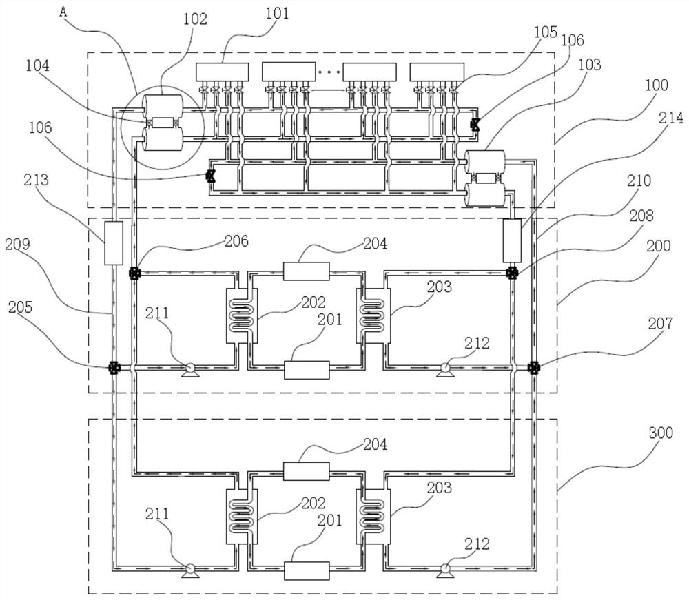
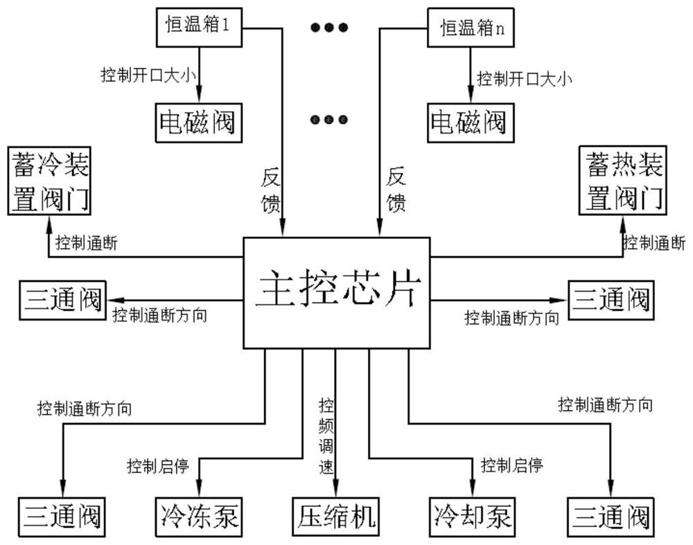
[0039] refer to Figure 1-Figure 2 , shows the structural block diagram and control block diagram of the thermostatic box control system in the embodiment of the present invention, the thermostatic box control system includes the central control system 200, the thermostatic box system 100 and the medium pipeline, and the central control system 200 is connected to the thermostatic box system through the medium pipeline 100. The incubator system 100 includes at least two incubators 101, wherein the central control system 200 is used to provide the temperature-regulating medium to the incubator system 100, and the central control system 200 can provide the incubator System 100 provides a temperature regulating medium.

[0040] In a specific implementation, the central control system 200 includes a main control system, which includes control elements such as a main control device, a temperature controller, a humidity controller, and a valve controller. Parts of the work, to achie...

Embodiment 2

[0054] Embodiment 2 is provided based on Embodiment 1. Embodiment 2 specifically describes the structure of the central control system 200. The central control system 200 includes a refrigeration device, a condensation device, an evaporation device and an expansion valve 204. Optionally, the refrigeration device is a compressor 201. , the condensing device is a condenser 203, and the evaporating device is an evaporator 202; wherein, the compressor 201 is connected to the evaporator 202 through a medium pipeline, the evaporator 202 is connected to the expansion valve 204, and the expansion valve 204 is connected to the condenser 203, and the condenser 203 is connected with the compressor The machine 201 is connected, and a refrigeration cycle is formed through the above connection, and the circuit is used to generate cooling medium and heating medium.

[0055] In a specific implementation mode, the compressor 201 uses the refrigerant in the medium pipeline to perform high-pressu...

Embodiment 3

[0060] Embodiment 3 is provided on the basis of Embodiment 2. Embodiment 3 further provides a backup control system 300. It can be understood that the configuration of the backup control system 300 is consistent with that of the central control system 200. The cooling medium pipeline of the backup control system 300 209 and the heating medium pipeline 210 are respectively connected to the incubator system 100 through the first breaking device 205, the second breaking device 206, the third breaking device 207 and the fourth breaking device 208, so that the incubator 101 of the present invention The control system has two sets of control systems. When the central control system 200 fails or the temperature adjustment medium supplied by the central control system 200 is insufficient, the main control device controls the opening and closing of each three-way valve and connects to the backup control system 300. At this time, the backup control The system 300 can supplement the tempe...


PUM


Abstract

The invention discloses a constant temperature box control system, which includes a central control system, a constant temperature box system and a medium pipeline. The central control system is connected to the constant temperature box system through the medium pipeline. The constant temperature box system includes at least two constant temperature boxes, wherein: It is used to provide temperature-regulating medium to the incubator system; the incubator system accepts the temperature-regulating medium and realizes temperature regulation; the medium pipeline is used to transport the temperature-regulating medium. This incubator control system concentrates the refrigeration system in the central control system, realizes centralized energy supply and distributed temperature and humidity control, thereby avoiding frequent start and stop of the individual incubator, reducing energy consumption and improving refrigeration efficiency. Efficiency, the volume of the terminal incubator is greatly reduced due to the reduction of refrigeration equipment, which is convenient for centralized arrangement, further realizes unified discharge, and reduces the layout of indoor room temperature air conditioners.

Description

technical field [0001] The invention relates to a thermostat system and a control method thereof, in particular to a centralized thermostat system and a control method thereof. Background technique [0002] The key components in many technical fields of batteries need to control their temperature when performing performance tests on batteries, battery modules and battery systems. Large battery testing laboratories require a large number of incubators. Although there are differences in the performance indicators of these incubators, their The working principle is to adopt the method of electric heating and electric cooling to realize the temperature control in the incubator through control. Each incubator includes a compressor, resistance wire heating and temperature control system. Because the single incubator contains The above components are bulky and occupy a large space; in large-scale laboratories, multiple incubators are required to run at the same time, which consumes...

Claims


Application Information

Patent Timeline
Patent Type & Authority Patents(China)
IPC IPC(8): F25D31/00F25D29/00G01R31/385
CPCF25D31/005F25D29/005G01R31/385
Inventor 姜久春弘利军
Owner SHENZHEN PRECISE TESTING TECH
Learn More