Phase-change cooling system and working method thereof

A phase-change cooling and working medium technology, applied in electrochemical generators, electrical components, circuits, etc., can solve the problems affecting the mileage of electric vehicles, high energy consumption of air-conditioning systems, low manufacturing and maintenance costs, etc., to ensure temperature distribution Good uniformity, temperature uniformity, and fast heat transfer rate

Active Publication Date: 2020-06-23
XI AN JIAOTONG UNIV
View PDF9 Cites 8 Cited by
  • Summary
  • Abstract
  • Description
  • Claims
  • Application Information

AI Technical Summary

Problems solved by technology

Among them, air-cooled heat dissipation is to take away the heat generated by the components by blowing air through the components. It has a simple structure, low manufacturing and maintenance costs, and low energy consumption. However, this method has a small specific heat capacity of the medium, poor heat dissipation effect, large internal temperature difference of the components, and large noise.
Liquid cooling heat dissipation is through direct contact between the cold plate and the components, the components transfer heat to the heat dissipation cold plate, and the liquid in the internal flow channel of the cold plate absorbs heat and flows out. Better, but flow resistance increases parasitic power dissipation
In addition, the heat transfer methods of air-cooled heat dissipation and liquid-cooled heat dissipation both use the sensible heat effect of the working fluid, so temperature

Method used


Image

  • Phase-change cooling system and working method thereof

Examples


Embodiment Construction

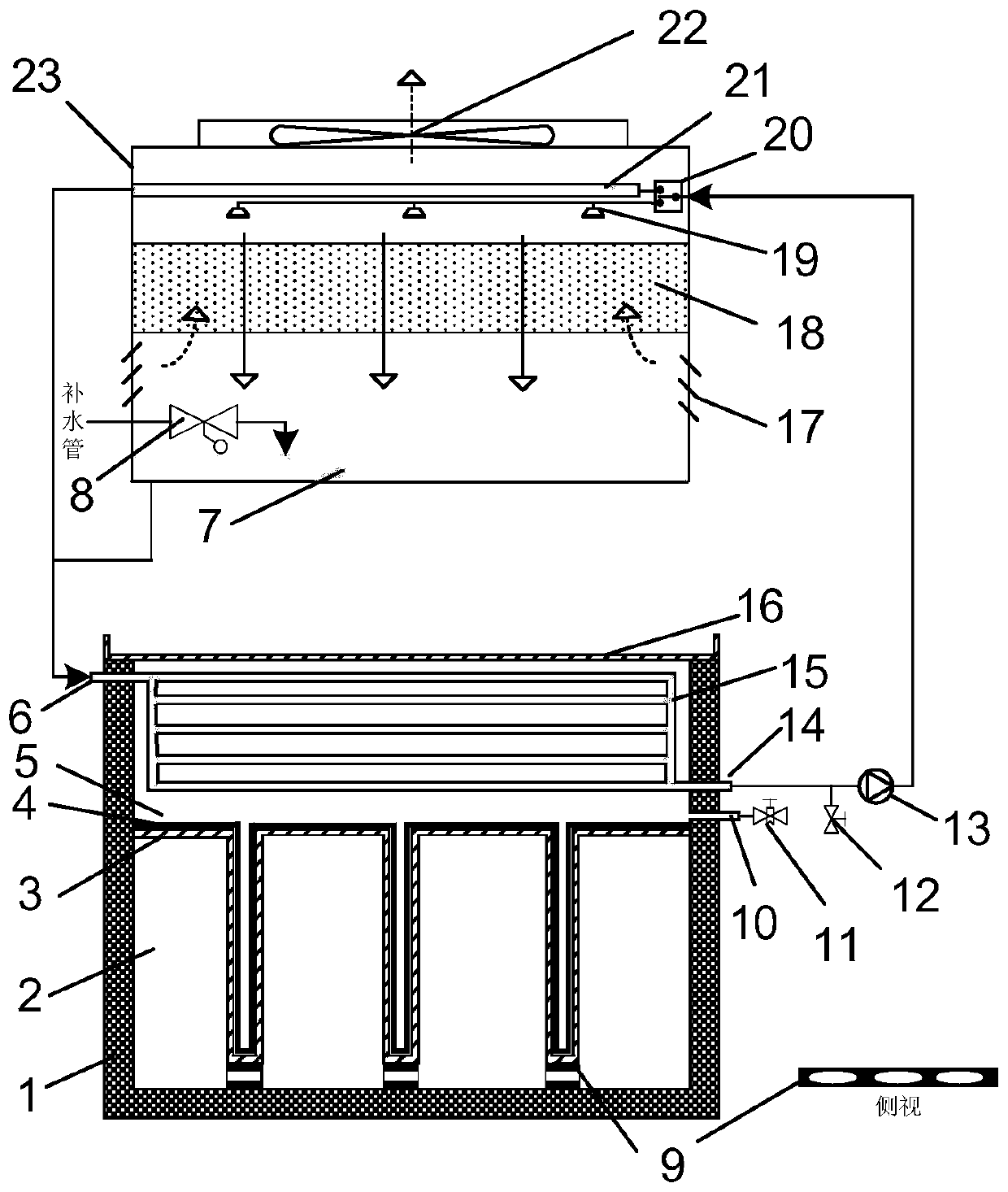
[0030] The present invention is described in further detail below in conjunction with accompanying drawing:

[0031] refer to figure 1, the phase change cooling system of the present invention includes a first split body 1, a second split body 23, a two-position three-way valve 20, a circulation pump 13 and a drain valve 12; the inside of the first split body 1 passes through the first partition 3 Divided into loading chamber 2 and evaporation chamber 5, the first partition 3 is a zigzag structure, and there is a thermal bridge 9 between the tooth end of the first partition 3 and the inside of the first split body 1, wherein the first partition 3 It is composed of a plurality of horizontal partitions and inverted vertical ribbed partitions connected end to end. The bottom of the vertical ribbed partitions is located on the side of the loading chamber 2, and a thermal bridge 9 is provided. The upper and lower sides of the thermal bridge 9 are respectively connected to the first...


PUM


Abstract

The invention discloses a phase-change cooling system and a working method thereof. The phase-change cooling system comprises a first split body, a second split body, a two-position three-way valve, acirculating pump and a water escape valve, the interior of the first split body is divided into an object carrying cavity and an evaporation cavity through a first partition, the first partition is of a sawtooth-shaped structure, a heat bridge is arranged between the tooth end of the first partition and the interior of the first split body, a capillary liquid guide core is arranged on the inner wall of the evaporation cavity, and a heating assembly is arranged in the object carrying cavity; a second partition is arranged at the top of the evaporation cavity, a condensation pipe is arranged inthe evaporation cavity, one end of the condensation pipe penetrates through the side wall of the evaporation cavity to be communicated with the condensation water inlet, and the other end of the condensation pipe penetrates through the side wall of the evaporation cavity to be communicated with the condensation water outlet; and a cooling heat exchanger, a spray pipe, a filling cavity and a wateraccumulation cavity are arranged in the second division from top to bottom. According to the system and the working method thereof, the working temperature of a cooled object can be effectively controlled to be 40 DEG C or below, the structure is simple, and energy consumption is low.

Description

technical field [0001] The invention belongs to the field of power electronics and battery heat management, and relates to a phase change cooling system and a working method thereof. Background technique [0002] New technologies such as 5G communication, big data, and new energy vehicles will profoundly change people's way of life. Related industries have gradually developed and will usher in a period of rapid development. Among them, power electronic components are the core components of communication technology, and one of the core components of new energy electric vehicles is battery technology. Both power electronic components and battery components need to work under certain temperature conditions, otherwise their reliability will be affected. and safety, and these components will generate heat during operation, so for systems such as communication networks, data centers, new energy vehicles, and new energy power generation, it is necessary to cool power electronic com...

Claims


Application Information

Patent Timeline
IPC IPC(8): H01M10/613H01M10/625H01M10/6563H01M10/6569
CPCH01M10/613H01M10/625H01M10/6563H01M10/6569Y02E60/10
Inventor 张兄文曹岗林彭年张强
Owner XI AN JIAOTONG UNIV
Why Eureka
Try Eureka