


Quick Research
Generate reliable direction feasibility study reports for your R&D in just a few steps.

Technical Q&A
Discover and master advanced knowledge NOW. Basics, ideas, possibilities, all at once.

Find Solutions
As an expert in R&D theories, this can generate solutions to your technical problems instantly.

Evaluate Feasibility
Analyze your overall solution with one click, know your potential R&D risks in advance.

Monitor Landscape
Get weekly tech updates, stay abreast of the latest tech innovations and key insights.
Gamma radiation imaging device and imaging method
An imaging device and gamma ray technology, which are applied in nuclear technology and application fields, can solve the problems of low detection efficiency, long acquisition time, and reduced directional information of imaging devices, so as to improve judgment effect, imaging quality, and high photon detection efficiency , the effect of high photon event information
- Summary
- Abstract
- Description
- Claims
- Application Information
AI Technical Summary
Problems solved by technology
Method used
Image

Examples
Embodiment 1
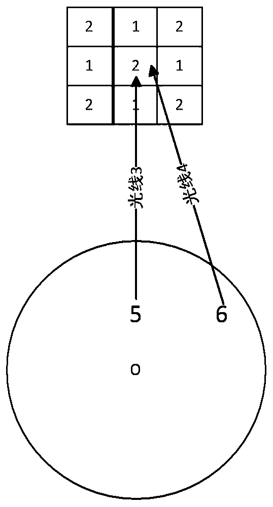
[0046] In this example, if figure 1 As shown, the imaging device includes 9 detectors, and the 9 detectors form 3 detector layers, which are distributed in 3 layers outside the object to be detected (such as the human body), and the first detector is sequentially from the inside to the outside. Detector layer, 2nd detector layer and 3rd detector layer. The nine detectors include two types of detectors, a first type detector 1 and a second type detector 2 . Moreover, any two adjacent detectors have different attenuation ratios to the photons.
[0047] Specifically, the first detector and the second detector are made of different materials. Using the imaging device of this embodiment, the light 3 from the position 5 of the detected object O and the light 4 from the position 6 respectively pass through the first detection before entering the second type detector 2 in the second detector layer. The first type detector 1 and the second type detector 2 in the detector layer, thus...
Embodiment 2
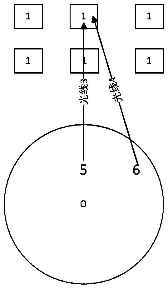
[0050] In this example, if figure 2 As shown, the imaging device includes 6 detectors, and the 6 detectors form 2 detector layers, which are distributed in 2 layers outside the object to be detected (such as the human body), and the first detector is sequentially from the inside to the outside. detector layer and the second detector layer. The six detectors are all the first type detectors 1 . Moreover, there is an interval between any adjacent two detectors, that is, there is an interval between the first detector layer and the second detector layer, and there is an interval between adjacent two detectors of the first detector layer. , There is also an interval between two adjacent detectors of the second detector layer.
[0051] Specifically, using the imaging device of this embodiment, the light 3 from the position 5 of the detected object and the light 4 from the position 6 are incident on the detector in the second detector layer, and the light from the position 5 of t...
Embodiment 3
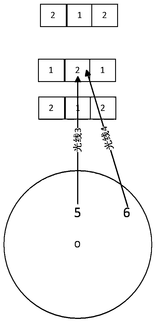
[0055] In this example, if image 3 As shown, the imaging device includes 9 detectors, and the 9 detectors form 3 detector layers, which are distributed in 3 layers outside the object to be detected (such as the human body), and the first detector is sequentially from the inside to the outside. Detector layer, 2nd detector layer and 3rd detector layer. The nine detectors include two types of detectors, a first type detector 1 and a second type detector 2 . There is an interval between two adjacent detector layers, and the interval between the first detector layer and the second detector layer may be different from the interval between the second detector layer and the third detector layer. Any two adjacent detectors have different attenuation ratios to the photons. The effect of judging the direction of the photon is further improved by spacing each layer with a certain distance.
[0056] Specifically, using the imaging device of this embodiment, the light 3 from the positi...
PUM
 Abstract
Description
Claims
Application Information
 - R&D Engineer
- R&D Manager
- IP Professional
- Industry Leading Data Capabilities
- Powerful AI technology
- Patent DNA Extraction
Browse by: Latest US Patents, China's latest patents, Technical Efficacy Thesaurus, Application Domain, Technology Topic, Popular Technical Reports.
© 2024 PatSnap. All rights reserved.Legal|Privacy policy|Modern Slavery Act Transparency Statement|Sitemap|About US| Contact US: help@patsnap.com