Supercharge Your Innovation With Domain-Expert AI Agents!

Semi-automatic welding equipment for outer walls of hulls

A semi-automatic welding and hull technology, applied in welding equipment, auxiliary welding equipment, welding/cutting auxiliary equipment, etc., can solve the problems of difficulty in guaranteeing welding accuracy, increase in cooling speed, and influence on welding quality, so as to improve welding efficiency and reduce Cooling speed, the effect of ensuring welding quality

Active Publication Date: 2020-06-26
芜湖易迅生产力促进中心有限责任公司
View PDF10 Cites 5 Cited by
  • Summary
  • Abstract
  • Description
  • Claims
  • Application Information

AI Technical Summary

Problems solved by technology

Although it realizes the automation of welding, for large hulls, it is very difficult to realize the precise driving of the welding device, and the welding accuracy is difficult to guarantee; secondly, the device cannot ensure that the distance between the welding torch and the welding surface remains constant. As a result, on the welding surface with large curvature changes, the welding quality of each part is uneven; thirdly, because the welding surface of the outer wall of the hull is exposed to the environment, it is inevitable that rust will occur. If the rust cannot be cleaned before welding, It will also have a certain impact on the welding quality. The traditional way is to use manual or other mechanical pre-cleaning, which is low in efficiency and high in cost; finally, since most of the current welding places are outdoors, if the weather with low outdoor temperature , due to the increase of cooling rate due to low temperature, more welding stress is likely to occur in the welded part, and at the same time, it will also have an adverse effect on the welded structure

Method used


Image

  • Semi-automatic welding equipment for outer walls of hulls
  • Semi-automatic welding equipment for outer walls of hulls
  • Semi-automatic welding equipment for outer walls of hulls

Examples


Embodiment Construction

[0042] In order to make the technical means, creative features, goals and effects achieved by the present invention easy to understand, the present invention will be further described below in conjunction with specific embodiments.

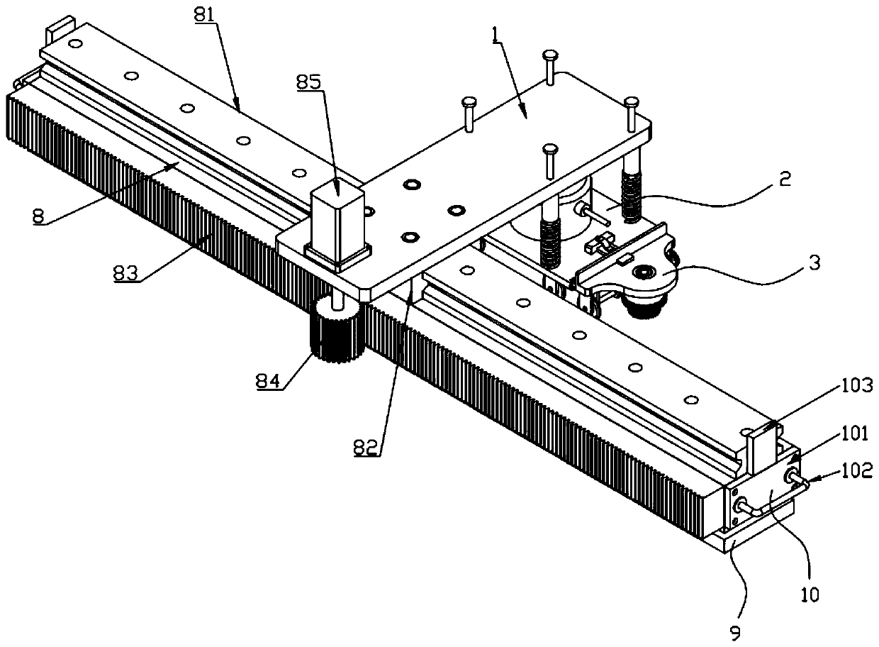
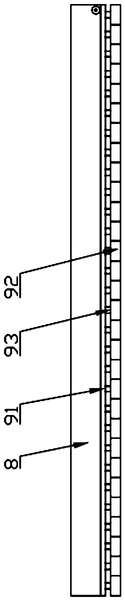
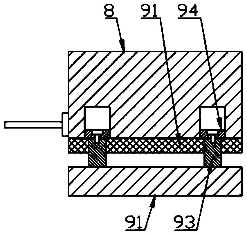
[0043] like Figure 1 to Figure 7As shown, a semi-automatic welding equipment for the outer wall of a hull includes a support frame 1, a flexible welding seat 2, a cleaning mechanism 3, a cooling mechanism 4, a base 8 and a flexible fitting assembly 9, and the top surface of the base 8 is provided with a slide rail 81, the support frame 1 is slidably connected to the slide rail 81 through a slider 82, a rack 83 is installed on one side of the base 8, the rack 83 is engaged with a drive gear 84, and the drive gear 84 is connected to the servomotor 85 At the output end, the servo motor 85 is installed on the support frame 1 on the same side as the rack 83, and the flexible fitting component 9 is installed on the bottom surface of the base 8 and is u...


PUM


Abstract

The invention discloses semi-automatic welding equipment for outer walls of hulls, and relates to the technical field of shipbuilding. The semi-automatic welding equipment comprises a supporting frame, a flexible welding seat, a cleaning mechanism, a cooling mechanism, a base and a flexible fitting assembly. According to the semi-automatic welding equipment, by the aid of guiding columns and springs, the distance between a base plate and the welding surface can be kept constant, that is, the distance between a welding head and the welding surface is constant, and the stability of the welding quality of the outer walls of the hulls under different curvature conditions is guaranteed effectively; at the same time of welding, through cooperation with the cleaning mechanism and the cooling mechanism on the front and back sides, on one hand, rust on the surface of the welding surface can be cleaned in advance, the welding quality is further improved, on the other hand, the heat of the welding heat affected zone is utilized effectively, air in a heat exchange pipe is heated and is used for preliminary cooling of a welding joint, the cooling speed is reduced, the welding quality is improved, three operations are performed synchronously, and thus the welding efficiency is improved remarkably.

Description

technical field [0001] The invention belongs to the technical field of shipbuilding, and in particular relates to a semi-automatic welding device for the outer wall of a ship. Background technique [0002] At present, the welding of the outer wall of the hull is mostly manual welding, which has high technical requirements for workers. During welding, workers need to stand for a long time, which is labor-intensive and prone to safety hazards. It is also difficult to accurately control the welding quality. [0003] Some devices capable of automatic welding have also appeared in the prior art, such as a kind of hull wall-climbing welding device whose Chinese patent publication number is CN103934596B. It can be freely stretched and bent within a certain limit to fit the surface of the hull, and maintain the balanced posture of the equipment mounting base, so that the welding torch can perform welding operations in a stable posture and complete the hull welding work efficiently. ...

Claims


Application Information

Patent Timeline
IPC IPC(8): B23K37/00B23K37/02B24B27/033B24B47/12
CPCB23K37/00B23K37/003B23K37/0217B24B27/033B24B47/12
Inventor 施性江
Owner 芜湖易迅生产力促进中心有限责任公司
Features
  • R&D
  • Intellectual Property
  • Life Sciences
  • Materials
  • Tech Scout
  • Unparalleled Data Quality
  • Higher Quality Content
  • 60% Fewer Hallucinations
Learn More