Environment-friendly printing machinery equipment for carton production
A technology of mechanical equipment and cartons, applied in printing, typewriters, printing devices, etc., can solve problems such as inkjet fluttering, lowering the printing quality of cartons, clogged nozzles, etc., to improve printing quality, accuracy and clarity , to avoid the effect of floating
- Summary
- Abstract
- Description
- Claims
- Application Information
AI Technical Summary
Problems solved by technology
Method used
Image
Examples
Embodiment 1
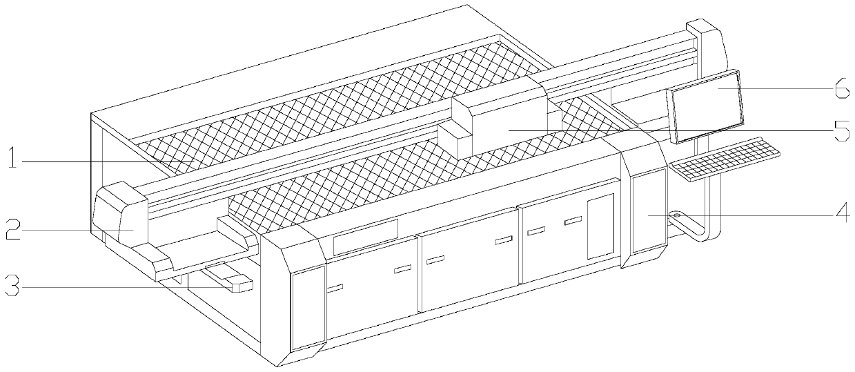
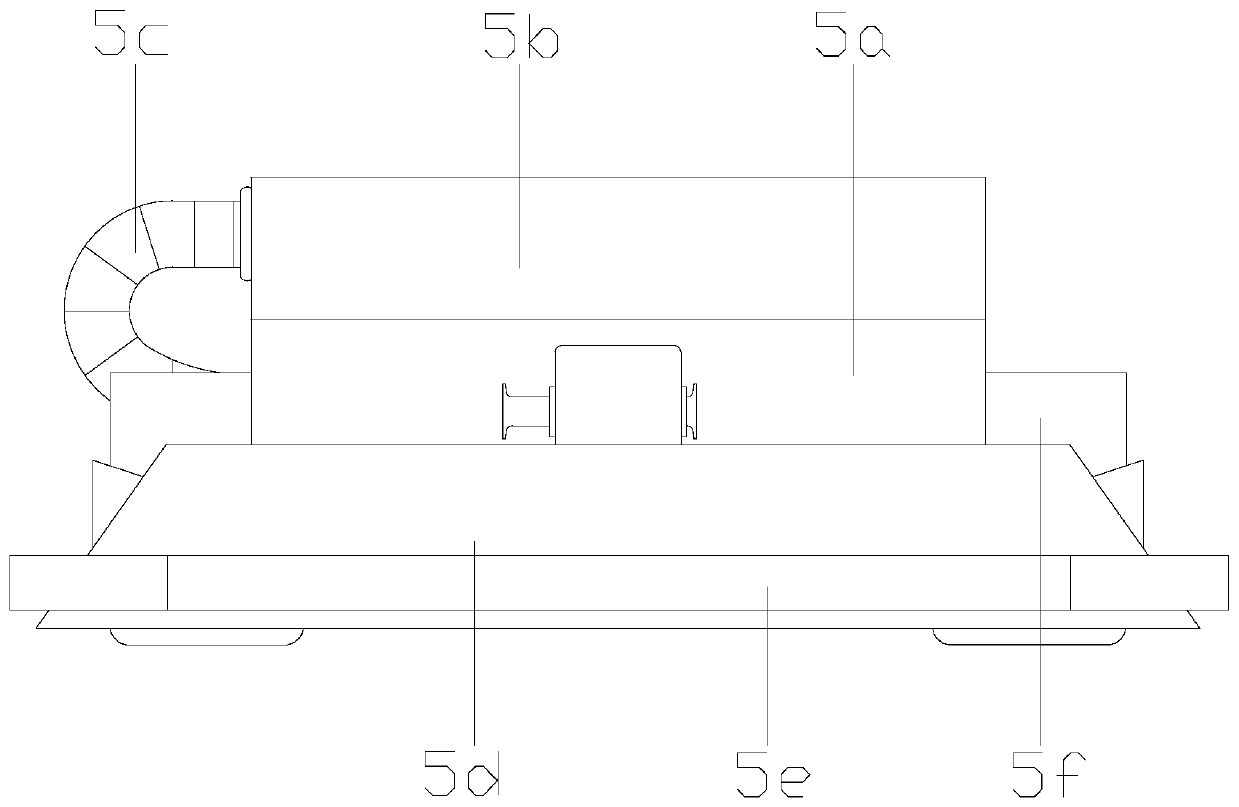
[0026] see Figure 1-Figure 5, the present invention provides a kind of environmental protection printing mechanical equipment for carton production, its structure includes carton processing table 1, horizontal sliding guide rail 2, longitudinal drag chain 3, equipment support seat 4, printer head 5, control center 6, all The equipment support base 4 has a rectangular structure and is installed horizontally. The longitudinal drag chain 3 is provided with two and installed on the left and right sides of the equipment support base 4 respectively. The drag chains 3 are interlocked, the bolts are installed on the right side of the equipment support base 4, the printer head 5 is installed in front of the transverse sliding guide rail 2 and is electrically connected to the control center 6, and the printer head 5 is controlled by the print head frame 5a, nozzle heat preservation structure 5b, power connector 5c, airflow chip removal device 5d, inkjet protection structure 5e, UV wate...
Embodiment 2
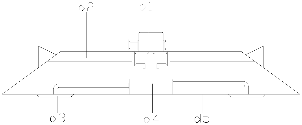
[0029] see Figure 6-Figure 7 The inkjet protection structure 5e is composed of a fluid discharge groove e1, a conduction switch e2, a discharge groove installation frame e3, and a splitter plate e4. The discharge groove installation frame e3 is horizontally installed outside the airflow chip removal device 5d, and the fluid The discharge groove e1 runs through and connects to the upper and lower sides of the discharge groove mounting frame e3, the splitter plate e4 is nested in the left and right ends of the discharge groove mounting frame e3, the conduction switch e2 conducts with the fluid discharge groove e1, and the fluid discharge The slot e1 and the pass switch e2 are perpendicular to each other. The conduction switch e2 is composed of a sealing plate e21, a switch fixing frame e22, a coil spring e23, a limit plate e24, and a discharge groove connector e25. The switch fixing frame e22 is inserted into the discharge groove mounting frame e3, and the The discharge groove...
PUM
 Abstract
Description
Claims
Application Information
 - R&D
- Intellectual Property
- Life Sciences
- Materials
- Tech Scout
- Unparalleled Data Quality
- Higher Quality Content
- 60% Fewer Hallucinations
Browse by: Latest US Patents, China's latest patents, Technical Efficacy Thesaurus, Application Domain, Technology Topic, Popular Technical Reports.
© 2025 PatSnap. All rights reserved.Legal|Privacy policy|Modern Slavery Act Transparency Statement|Sitemap|About US| Contact US: help@patsnap.com


