
Method and system for lateral stability control of distributed drive electric vehicle

A stable control method and a stable control technology, applied in the direction of the control device, etc., can solve the problems that affect the accuracy of the model, cannot be applied, and the tire parameters deviate from the nominal value, etc., to achieve the effect of improving the yaw stability

Active Publication Date: 2021-05-11
BEIJING INSTITUTE OF TECHNOLOGYGY
View PDF5 Cites 0 Cited by
  • Summary
  • Abstract
  • Description
  • Claims
  • Application Information

AI Technical Summary

Problems solved by technology

However, the working conditions during the driving process of the vehicle are complex, and it is impossible to stay in the driver's linear control range at all times, and even often in dangerous extreme working conditions. The finite-dimensional dynamic model cannot accurately describe the real dynamic characteristics of the vehicle, and the model mismatch Serious; at the same time, the tire parameters greatly deviate from the nominal value, making the model error serious
In addition, many vehicle parameters cannot be accurately known in advance, and the road adhesion coefficients of different driving conditions are quite different, which greatly affects the accuracy of the model
Therefore, the above factors have a greater impact on the accuracy of the vehicle dynamics model
For the vehicle kinematics model, on the one hand, it is less robust to sensor measurement errors and sensor drift; on the other hand, it is easy to lose observability in steady-state conditions
To sum up, both the vehicle dynamics model and the vehicle kinematics model have limitations and cannot be applied to all driving conditions of the vehicle

Method used


Image

  • Method and system for lateral stability control of distributed drive electric vehicle
  • Method and system for lateral stability control of distributed drive electric vehicle
  • Method and system for lateral stability control of distributed drive electric vehicle

Examples


Embodiment

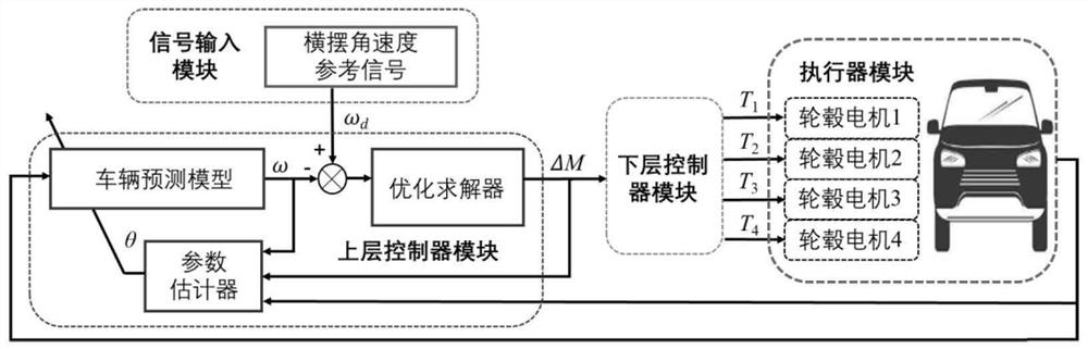
[0083] figure 1 It is a schematic diagram of the control structure in the embodiment of the present invention, such as figure 1 As shown, the control structure of the present invention includes four parts: a signal input module, an upper controller module, a lower controller module and an actuator module.

[0084] 1. The function of the signal input module is to input a signal to the upper controller: yaw rate reference signal.

[0085] 2. The upper controller module consists of three parts: vehicle prediction model part, optimization solver part and parameter estimator part. The function of this module is to solve the direct yaw moment, which is used to improve the yaw stability of the vehicle.

[0086] 3. The role of the lower controller module is to evenly distribute the direct yaw moment generated by the upper controller to the actuator.

[0087] 4. The actuator module is an actuator, including: 1. Hub motor, used to execute the torque distributed by the lower controlle...


PUM


Abstract

The invention discloses a lateral stability control method and system of a distributed drive electric vehicle. Establish a vehicle yaw rate prediction model based on vehicle yaw rate historical data, vehicle direct yaw moment historical data, and noise data. This model does not depend on variable vehicle parameters and environmental parameters that cannot be accurately known in advance. Based on this model, According to the current data of the vehicle yaw rate, the recursive least squares method is used to determine the parameter vector in the model, and the vehicle yaw rate is predicted according to the parameter vector and the current data of the vehicle yaw rate, and the predicted value of the vehicle yaw rate is obtained. Since the model parameters are time-varying By estimating and updating the parameter vector in real time, the vehicle model is adaptive and can be applied to all driving conditions of the vehicle; the model has certain robustness to sensor measurement errors, and the vehicle yaw rate measurement value The noise in has a certain filtering effect, which can improve the yaw stability of the vehicle.

Description

technical field [0001] The invention relates to the technical field of electric vehicle stability control, in particular to a distributed drive electric vehicle lateral stability control method and system. Background technique [0002] The vehicle models adopted by the existing vehicle stability controllers are mainly divided into two categories: vehicle dynamics models and vehicle kinematics models. When the driver is in the linear control range, the vehicle parameters and road adhesion coefficient are accurate, and the tire parameters are at the nominal value, the vehicle dynamics model has higher accuracy. However, the working conditions during the driving process of the vehicle are complex, and it is impossible to stay in the driver's linear control range at all times, and even often in dangerous extreme working conditions. The finite-dimensional dynamic model cannot accurately describe the real dynamic characteristics of the vehicle, and the model mismatch Serious; at ...

Claims


Application Information

Patent Timeline
Patent Type & Authority Patents(China)
IPC IPC(8): B60W30/02B60W40/10B60W40/12B60W50/00
CPCB60W30/02B60W40/10B60W40/12B60W50/00B60W2050/0031
Inventor 赵泽顾亮秦也辰
Owner BEIJING INSTITUTE OF TECHNOLOGYGY
Learn More