Cableway self-propelled transportation equipment
A self-propelled transportation and cableway technology, applied in cable railways, transportation and packaging, motor vehicles, etc., can solve the problems of hydraulic pump failure, large energy loss, limited quantity, etc., and achieve the effect of convenient operation and improved applicability
- Summary
- Abstract
- Description
- Claims
- Application Information
AI Technical Summary
Problems solved by technology
Method used
Image
Examples
Embodiment 1
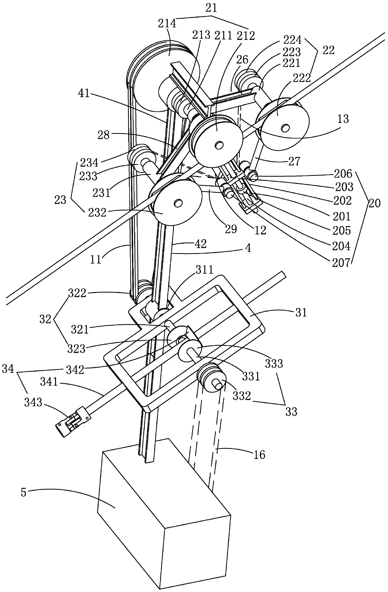
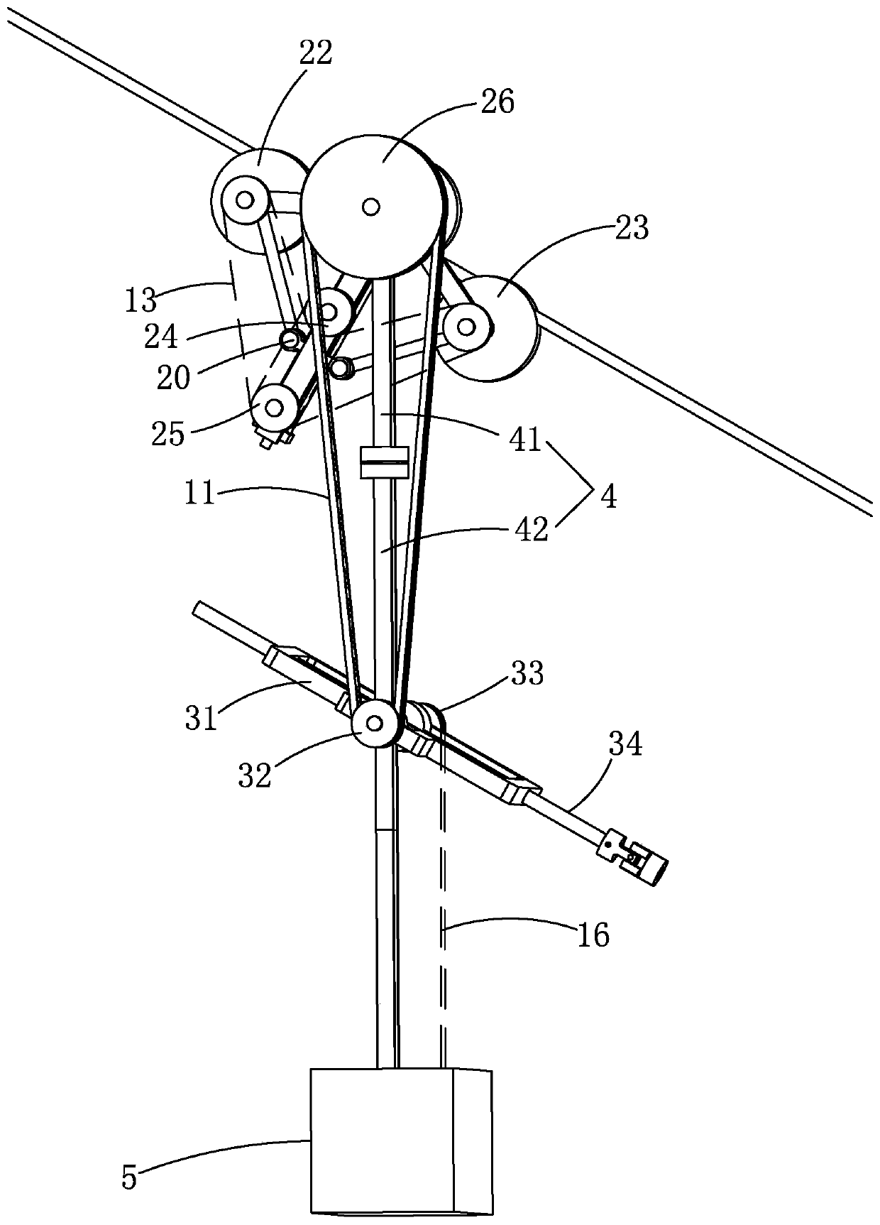
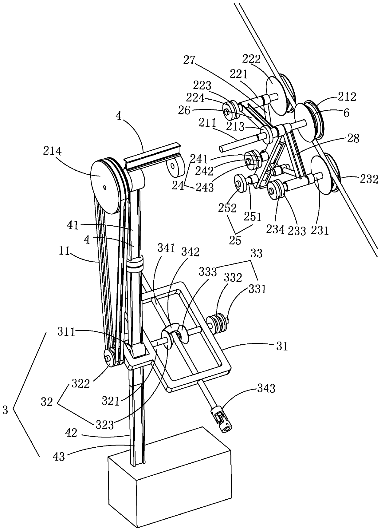
[0056] Embodiment 1, combining Figure 1-4 As shown, a cableway self-propelled transportation device includes a transportation device 1 , and the transportation device 1 includes a sliding adjustment mechanism 2 , a transmission mechanism 3 and a pulling arm 4 .
[0057] to combine Figure 15 As shown, the pull arm 4 includes an upper pull arm portion 41 and a lower pull arm portion 42, the upper pull arm portion 41 includes a beam 411, a first bushing 412 and a second bushing 413, the first bushing 412 and the second bushing 413 are respectively fixed under the two sides of the beam 411, the middle part of the lower arm part 42 has a shaft hole 421, and the lower part of the lower arm part 42 is provided with a hook 43 for hanging articles or power source 5, and The upper arm part 41 and the lower arm part 42 are connected together in a rotational manner. The sliding adjustment mechanism 2 is movably arranged on the upper pull arm part 41 , and the transmission mechanism 3 ...
Embodiment 2
[0081] Example 2, combined with Figure 10 As shown, the difference between Embodiment 2 and Embodiment 1 is that: multiple transportation devices 1 are suspended on the cableway rope, and the transportation device 1 hooked with a power source 5 (internal combustion engine or electric motor) is an active transportation device 1, The transport device 1 with the goods hooked is a passive transport device 1, so a plurality of transport devices 1 are suspended on the cableway rope, and the transport device 1 and the transport device 1 are connected by a universal joint 343, and the universal joint 343 One end is connected to the drive reversing shaft 341 of the previous transport device 1 , and the other end of the universal joint 343 is connected to the drive reversing shaft 341 of the next transport device 1 .
[0082] In Embodiment 2, the power source 5 of the active transportation device 1 drives the tenth transmission assembly 33 to rotate through the sixth transmission belt ...
Embodiment 3
[0085] Example 3, combined with Figure 11 As shown, the difference between Embodiment 3 and Embodiment 1 is that the transmission mechanism of Embodiment 3 only has a power source 5, and the power source 5 is suspended at the lower end of the pull arm, and the power source 5 and the first transmission assembly 21 of the transportation device 1 A first transmission belt 11 is arranged between them, the first transmission belt 11 is a transmission belt, and the transmission mechanism 3 drives the first transmission assembly 21 to rotate through the first transmission belt 11 .
PUM
 Abstract
Description
Claims
Application Information
 - R&D
- Intellectual Property
- Life Sciences
- Materials
- Tech Scout
- Unparalleled Data Quality
- Higher Quality Content
- 60% Fewer Hallucinations
Browse by: Latest US Patents, China's latest patents, Technical Efficacy Thesaurus, Application Domain, Technology Topic, Popular Technical Reports.
© 2025 PatSnap. All rights reserved.Legal|Privacy policy|Modern Slavery Act Transparency Statement|Sitemap|About US| Contact US: help@patsnap.com


