Airflow guide plate for spinneret of melt-blown loom

A deflector and spinneret technology, applied in the direction of melt spinning, non-woven fabrics, textiles and papermaking, etc., can solve the problems of no guide tooth design, finished product level restrictions, uneven distribution of melt-blown fabric fibers, etc. To achieve the effect of enhancing stability

Inactive Publication Date: 2020-06-26
ZHENJIANG DONGYI MACHINERY
View PDF0 Cites 9 Cited by
  • Summary
  • Abstract
  • Description
  • Claims
  • Application Information

AI Technical Summary

Problems solved by technology

[0003] Melt-blown cloth uses high-speed hot air flow to draw the thin stream of polymer melt extruded from the spinneret hole of the die head; the products currently on the market use small holes to divide the flow and then enter the air cavity, and the jet flow channel is a narrow gap to exit the air There is no guide tooth design of the present invention; and due to the uneven distribution of air flow, the fiber grinding nozzle direction of the melt-blown cloth will be unevenly distributed, and the finished product level of the cloth is limited, thereby forming ultra-fine fibers and collecting them on the condensation net curtain or drum At the same time, it is self-adhesive and becomes a melt-blown nonwoven fabric; the quality of the spinneret assembly directly determines the product performance of the melt-blown nonwoven fabric

Method used


Image

  • Airflow guide plate for spinneret of melt-blown loom
  • Airflow guide plate for spinneret of melt-blown loom
  • Airflow guide plate for spinneret of melt-blown loom

Examples


Embodiment Construction

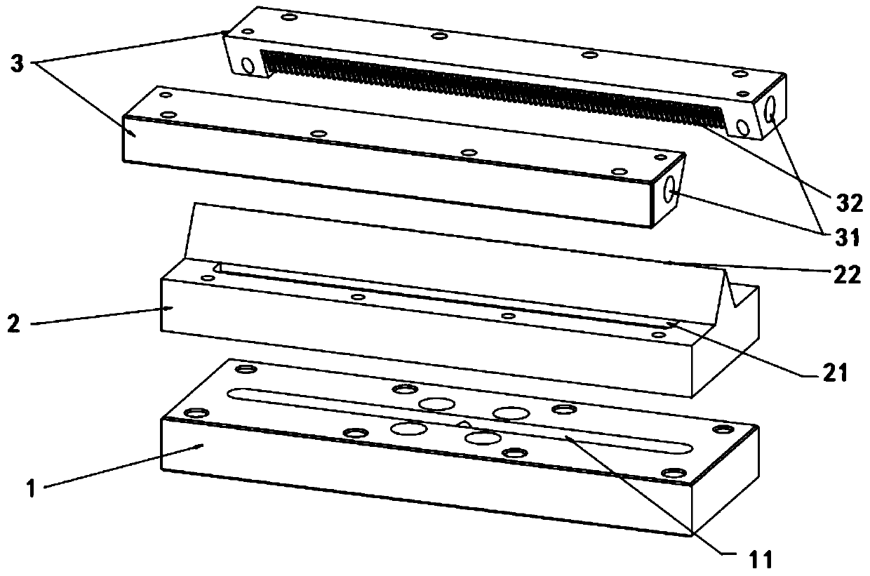
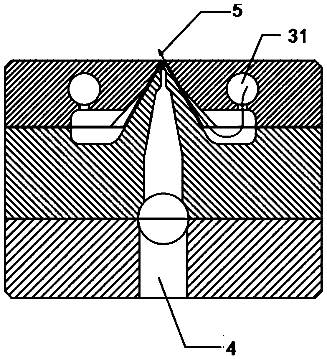
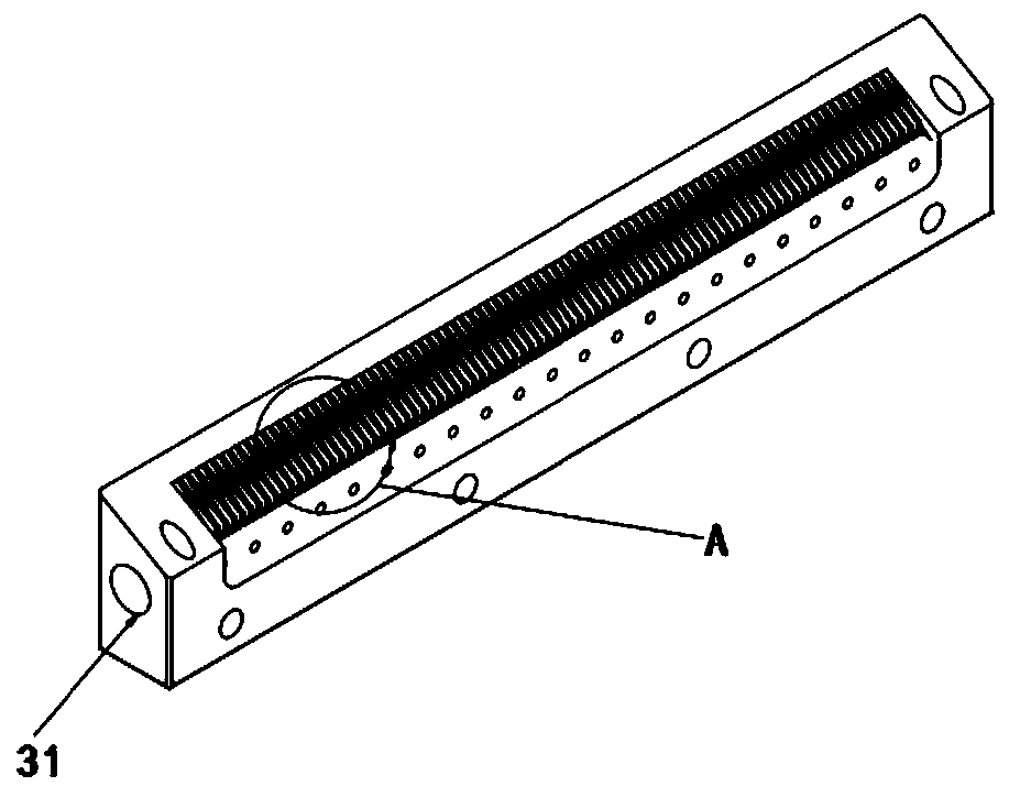
[0016] like figure 1 -As shown in Figure 5, the present invention includes a melt fluid feeding plate, a spinneret main body, and a gas jet flow plate; the melted chemical fiber raw material enters the melt channel of the spinneret main body from the heat flow groove of the melting fluid feeding plate, The spinneret hole of the spinneret main body forms a filamentary outflow; the high-temperature and high-pressure gas enters the air cavity formed by the spinneret main body and the gas jet plate from the air inlet of the gas jet plate; and then flows from the air cavity to the gas jet The diversion groove of the plate moves, and the gas is ejected under pressure to form a symmetrical high-speed airflow with a certain angle with the spinneret hole of the spinneret main body, thereby pulling the chemical fiber melt ejected from the spinneret main spinneret hole to form microfibers.

[0017] A further design is that: the airflow deflector is made of SUS431, SUS630, SUS440C, S136H...


PUM


Abstract

The invention discloses an airflow guide plate for a spinneret of a melt-blown loom. The airflow guide plate comprises a melt feeding plate and a spinneret plate body, wherein the bottom of the spinneret plate body is connected with the melt feeding plate; a melt flow channel is formed in the upper surface of the melt feeding plate; and the melt flow channel communicates with an inner cavity of the spinneret plate body to form a molten mass channel. The airflow guide plate is characterized in that symmetrical air jet plates are arranged on the two sides of a protrusion on the upper portion ofthe spinneret plate body; an air cavity is formed in the upper surface of the spinneret plate body, and a row of spinneret orifices which are evenly distributed are formed in the top end of the protrusion; air inlet holes and guide grooves are formed in the air jet plates, the air inlet holes communicate with the air cavity, form guide flow through the guide grooves and form symmetrical high-speedair flow with a certain included angle with the spinneret orifices. According to the airflow guide plate, air jet is more stable, so that the traction of melt fibers is more stable, the size is uniform, and the quality of melt-blown non-woven fabric is improved.

Description

technical field [0001] The invention relates to an airflow deflector for a spinneret nozzle of a meltblown loom. Background technique [0002] The melt-blown cloth filter material is made of polypropylene superfine fibers randomly distributed and bonded together. The appearance is white, flat and soft. The material fiber fineness is 0.5-1.0 μm. The random distribution of fibers provides more thermal bonding between fibers. Opportunity, so that the melt-blown gas filter material has a larger specific surface area and higher porosity (≥75%); after high-pressure electret filtration efficiency, the product has the characteristics of low resistance, high efficiency, and high dust holding capacity. [0003] Melt-blown cloth uses high-speed hot air flow to draw the thin stream of polymer melt extruded from the spinneret hole of the die head; the products currently on the market use small holes to divide the flow and then enter the air cavity, and the jet flow channel is a narrow ga...

Claims


Application Information

Patent Timeline
Patent Type & Authority Applications(China)
IPC IPC(8): D01D5/098D04H1/56
CPCD01D5/0985D04H1/56
Inventor 陈立军
Owner ZHENJIANG DONGYI MACHINERY
Why Eureka
Try Eureka